Continue to Site

Welcome to EDAboard.com

Welcome to our site! EDAboard.com is an international Electronics Discussion Forum focused on EDA software, circuits, schematics, books, theory, papers, asic, pld, 8051, DSP, Network, RF, Analog Design, PCB, Service Manuals... and a whole lot more! To participate you need to register. Registration is free. Click here to register now.

Capacitive Drop Drive Topology explanation

Status
Not open for further replies.

yassin.kraouch

Advanced Member level 2
Joined
Jul 5, 2009
Messages
631
Helped
40
Reputation
80
Reaction score
40
Trophy points
1,308
Activity points
5,094
Hi,
can anyone explain to me the capacitive drop drive topology ? how it works ? what is the role of the capacitor ?
thanks,
 

thank you, but this explanation is not so clear for me,
 

The capacitor charge opposes the supply volt level to some extent, at each moment.

Hence the load receives reduced AC voltage.

The capacitor produces reactance rather than resistance. This allows the voltage drop to be achieved without the generation of wasteful heat.

A coil (or choke) operates in a similar manner.

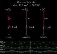
Here is a simulation comparing the effects of resistive, capacitive, and inductive voltage drops.


The capacitor and coil values need to be tailor adjusted to the load and AC frequency.

Notice that the capacitor advances the sinewave. The inductor delays it.
 

good, the problem is i did not understand the mathematical result ? how the voltage will be dropped ? i did not uderstand how they found this result theorically
 

The capacitor and resistor can be seen as forming a high pass filter. There are formulae for calculating performance at various frequencies.

Notice it does not work to use only the basic impedance formula for capacitive reactance:

X = 1 / ( 2 * Pi * F * C )

If we were to use this equation by itself, the capacitor should be 66 uF. However in my schematic above, the capacitor is 38 uF. That turns out to be the value that halves the AC volt level across the 40 ohm load.

The correct calculation has to do with drawing a phasor diagram (parallelogram whose vectors are a certain degree).


Webpage with interactive geometric diagram:

**broken link removed**
 

Yes, the electroschematics website describes an led load being powered by a capacitive drop supply.

I'm not sure which we would say: whether the led load complicates things, or whether it simplifies things.

It's all right to use the simpler formula with the led, because it creates its own voltage drop, and thus it automatically causes a greater drop across the capacitor than there would be with a plain resistive load.

LED's are non-linear components.

I used the idea of a resistive load because it is linear. It is a simpler case with which to illustrate the concept of voltage drop.
 

Status
Not open for further replies.

Similar threads

Part and Inventory Search

Welcome to EDABoard.com

Sponsor

Back
Top