Continue to Site

Welcome to EDAboard.com

Welcome to our site! EDAboard.com is an international Electronics Discussion Forum focused on EDA software, circuits, schematics, books, theory, papers, asic, pld, 8051, DSP, Network, RF, Analog Design, PCB, Service Manuals... and a whole lot more! To participate you need to register. Registration is free. Click here to register now.

capacitance water level sensor

Status
Not open for further replies.

abdoalghareeb

Member level 5
Member level 5
Joined
Feb 5, 2010
Messages
84
Helped
1
Reputation
2
Reaction score
1
Trophy points
1,288
Activity points
1,981
I try to build capacitance water level sensor.
It is 1 meter plastic tube (1 inch diameter), and two thin plates of aluminum covers the tube, the distance between plates are 1 cm.Then I Insulate the tube by adhesive tape.
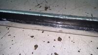


That tube is the capacitor of 555 astable circuit.
the output frequency is measured by atmega16 to determined the tank water level.

The problem are:
The output frequency is not steady on any steady level (50cm level == 15.1 khz +- 0.3khz).
The length of wire between the tank and main circuit changes the frequency.
 
Last edited by a moderator:

I wonder if you were able to make a solid connection between aluminum and wires? Solder won't take to aluminum.

The reason it could be important is, resistance might change with slight physical movement of the joint. Sometimes I've done electrical experiments with aluminum foil, clipping jumper wires to it. I cannot always be sure the connection is really low ohm, unchanging. That is to say, it's a 'scratchy' connection.

15.1 khz +- 0.3khz

This is 2 percent variation. This doesn't seem too bad.
 

The output frequency is not steady on any steady level (50cm level == 15.1 khz +- 0.3khz).
The length of wire between the tank and main circuit changes the frequency.

There will always be nominal variations and fluctuations; consider that a handmade system gave reasonable result.

That the connecting wire also contribute to the capacitance is expected; you may consider using a capacitance to voltage converter (just like capacitor microphones) at the top point in the tube.

The you will get a voltage signal that will not be depending on the length of the wire.

If the tube is close to the metal wall of the tank, the capacitance may also be affected; best position is in the middle.
 

Most likely you have a large common mode noise interfering with a differential current source, sense.

Try a large CM balun or ferrite sleeve or twin coupled choke to the twisted pair to raise CM impedance and thus CMRR but keep DM impedance relatively low compared to Zc(f)

If that fails, reduce area of loop with a smaller gap . water has a dielectric constant of 80 and pvc is ~3 but it is in series with electrodes to water.. Thus it is like a variable large cap in series and parallel with a small caps.

Noise can be measured on each pin and Vcc and gnd with care to isolate further.

LC oscillator might reject noise more , depending on nature of noise

Do you have an LCR meter?

Can you vary the center frequency vs stability and plot?
Noise current or voltage will depend on Zc(f) as will excitation. Obviously you want to improve SNR or excitation to noise ratio in a low Q measurement device prone to EMI noise.

CM choke.... F vs stability... noise ingress.. Vcc noise, shielding....
 
Last edited:

Status
Not open for further replies.

Part and Inventory Search

Welcome to EDABoard.com

Sponsor

Back
Top