Continue to Site

Welcome to EDAboard.com

Welcome to our site! EDAboard.com is an international Electronics Discussion Forum focused on EDA software, circuits, schematics, books, theory, papers, asic, pld, 8051, DSP, Network, RF, Analog Design, PCB, Service Manuals... and a whole lot more! To participate you need to register. Registration is free. Click here to register now.

Cannot locate Xenon flash tube and trigger transformer...

Status
Not open for further replies.

grizedale

Advanced Member level 3
Joined
Jun 13, 2011
Messages
838
Helped
17
Reputation
34
Reaction score
17
Trophy points
1,298
Activity points
8,804
Hello,

We are using a xenon flash tube and trigger transformer.

Our new xenon tube does not always trigger and we notice that the trigger circuit is slightly different.
We are suspicious that the trigger circuit is incorrect, and wish to find the datasheet for the xenon flash tube and the trigger transformer, but we can find neither of these things.

We are told that the xenon tube is AGA0017 DDS4 by Perkin Elmer
We are told that the Trigger transformer is ZS1052-SUL(H)-V02, again by Perkin Elmer.

However, i went to the Perkin Elmer website and they do not even appear to sell xenon tubes.......and googling the part numbers reveals nothing.

I am wondering of the xenon tubes division of Perkin Elmer has been sold off to somebody else...but who?

..i wonder this because i did manage to find this document on flash tubes by Perkin Elmer...

**broken link removed**

......we are using the trigger circuit like on page 4, part (1) "Capacitive external triggering".

Our thyristor is BT168G:-
**broken link removed**

The capacitor is 47nF, 250V, X7R, and the resistor is 22MegOhms

Our Bulk voltage across the tube, when it is triggered is 200V, this is provided by a 22uF, 250V electrolytic which is re-charged by a buckboost converter when the flash has discharged it.

Our trigger pulse, from the microcontroller to the thyristor is 3V high and 10us long...there is 1K in series with the thyristor gate drive, so the maximum the gate current could be would be 3mA.

We only flash once every 810ms. (I put a 0R1 sense resistor in series with the tube, and noticed that the tube current is 21 A peak, and the current has pretty much all died away after 200us.)
-The flash though, appears to the naked eye , to last longer then 200us.


(I am hoping that there is no ultra-violet in the light from the xenon tube?)


I did manage to find this on trigger transformers of perkin elmer but ours is surface mount so cant be any of these.....
**broken link removed**
 
Last edited:

P.S.: I think the trigger time constant is too high. The capacitor doesn't fully charge when flashing periodically. You should have also checked the flash capacitor voltage.

I did manage to find this on trigger transformers of perkin elmer but ours is surface mount so cant be any of these.....
??? Most transformers in the catalog are surface mount. But actually the shape doesn't matter. You can assume that most available trigger transformers on the market have similar windings ratios. Any of these fits.
 

Attachments

  • ZS1052.pdf
    97 KB · Views: 121
Last edited:
Thanks, so you think we need to reduce the 22Meg resistor?

FvM It appears from the datasheets that you kindly supplied that the tube should have a minimum of 170V across it when it is flashed. I wonder if this voltage needs to be more in colder ambient condictions?...and can it be less in hotter ambient conditions.

From the data it appears also that we can extend the life of the tube by using a 100nF capacitor instead of the 47n that we use in the trigger circuit.

Also, our trigger pulse to the gate of the thyristor is merely 10us long......surely a thyristor will have a very slow rise time and our trigger pulse from the uC is too narrow......i bet the thyristor doesnt even turn on in 10us?
 

From the data it appears also that we can extend the life of the tube by using a 100nF capacitor instead of the 47n
The trigger pulse doesn't wear the tube, only the flash itself. It's the total energy running through the tube that sputters electrode metal and limits tube lifetime.

I'm not aware of a temperature dependency of minimum tube voltage, may be. Perhaps you shouldn't operate it exactly at the minimum.
 
thanks, though on page 3 of your document about trigger transformers which you kindly provided above, it clearly states that you get a lifetime of 1e6 flashes with a 47nF cap, but 3.6e6 flashes if you use 100nF
 

I see what you mean. It's in the flashlamp document, not the trigger transformer document.

The columns on page 3 are continuing the table on page 2. 47 n/1e6 flashes is specified for AGA0017, 100n/3.5e6 flashes for BGA1020. These are flash tubes of different power rating. The document suggests a higher trigger energy for the second tube. It's also saying that the primary trigger DC voltage should be 170V, not only a fraction of it by using an unsuitable RC time constant.
 
I just saw this old thread. Dear Grizedale, the plasma EM wave in xenon gas is almost like the sun fairly flat from 150nm to > 1300nm IR, but at least no gamma and not much Xray. But yes there is lots of UV.

Like all gas tubes and SCR's they also have a negative resistance characteristic and the bigger the electrodes, the lower the ESR.
There may also be a 1/4λ and 1/2λ effects on resonance for emissions based on the electrode pitch of 17mm and a µ value of 2~3, you can work out the microwave frequency of the burst. All in all, a pretty good impulse generator. Better tubes will have a shunted helix around the glass as an external shield for RF.

The time constant of the tube current is a product of the capacitance * total resistance of the cap and the tube in conduction mode. Now I never thought about this before, but if you had a negative 1 Ω in series with a positive 1Ω does that give you 0 dead short. The answer is yes i believe and this represents a system 0 ESR until the point where the "squelch voltage?" Vs is reached and the impedance polarity quickly inverts to positive impedance as the voltage and current continues to decay to zero.

This pulse ought to interfere with every radio system up to 17mm 1/2λ and a bit more with harmonics.

**added correction**
With L/W ratio < 5
"bigger the electrodes, the lower the ESR. "
This means electrode controlled ESR or "electrode stabilized".
With longerer L/W ratio > 5, the conduction fills the tube walls and becomes " wall stabilized " or wall controlled ESR "

There are many parameters to consider besides shape of the tube and case for heat reduction in xenon selection;
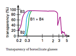
Watt-Sec of power, trigger voltage range, Colour temperature of emission controlled by gas blending, flash rate per second, Spectral control UV in the Bisilicate Glass, spectrum of IR from high impedance emissions, the xenon gas pressure which increases trigger voltage but also efficacy, EMI control and thermal heat transfer of tube design, Current density of flash affect on spectral emission and efficacy by current density ( 100~ 7000 A/ sq.cm) etc etc**
What are these flash tubes primarily used for? photoimaging? visual effects?
 
Last edited:
but if you had a negative 1 Ω in series with a positive 1Ω does that give you 0 dead short.
All thes impedance numbers are differential ones, valid for a specific I/V point and plama state. Fortunately, flashlamp discharge currents are finite under usual operation conditions, even with low ESR foil capacitors and always with photo flashes that use electrolytic capacitors. Up to several 1000 A aren't uncommon, however.

In high power flash lamp applications, pulse forming chokes ma^y be reasonable to extend the tube lifetime.

I'm not aware of microwave emissions observed in usual flashlamp applications, but may be there are. More trivial wide band emissions caused by the pulse current can be mainly expected with low ESR/ESL capcitors and respective µs pulse width. Photo flash applications have up to several 100 µs pulse widths (unless the discharge is stopped by the automatic exposure control through a thyristor).
 
Effectively all ESR measurements are differential where Rs= ∆V/∆I {a.k.a. ESR} is represented by the slope of the V-I curve where ESR is constant over a flat sloped region.

( for further research find how Negative resistance devices can be used to amplify signals or produce extremely bright broad spectrum impulse or steady state emissions all the way from tiny ESD pulse to the fusion reaction in stars such as our Sun. )

There are literally millions of applications of plasma discharge effects used in every field of science from Cancer research, electro-spectroscopy, DNA research, and even commercial lighting with thimble size bulbs which are impressively bright,driven by a high power microwave oven size generator to drive the tiny tube and a Faraday Cage to shield them for humans. Plasma resonators make effective microwave jammers with high levels of incoherent emissions centred around resonant lengths between electrodes. Varying the pressure and mix of inert gas changes a huge range of spectral bandwidth and efficacy while affecting the trigger voltage, ESR and emission shape levels. Selective RGB colours are controlled carefully in Plasma inert gas mixes and pressures achieving high contrast ratios with high saturation.

Plasma is defined in many fields of science and may exhibit behaviours of a "quasi" solid-liquid-gas, where the common characteristic is the ionization and deionization process of charged atomic and sub-atomic particles. e.g. in Aurora Borealis. The actual medium and purposes are as diverse as colour TV's

Different types of Bi-Silicate and Quartz glass can aid is blocking UV emissions or handle higher temperatures depending on application.
Screen shot 2012-06-25 at 9.05.23 AM.PNG

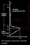
The point at which the tube becomes max current is the Zero ESR point and also the point where the device starts to behave as a linear resistor controlled by the electrode resistance down to the residual threshold Vr, when current is squelched by insufficient energy to sustain ionization to de-ionization emission exchange.
Screen shot 2012-06-25 at 8.44.30 AM.PNG

From the graph we see 4 thresholds Vr, Vs, Vo, Vz which are controlled by the inert gas type & pressure, electrode tube aspect ratio and size.

Xenon and Krypton are popular for their broad visible spectrum emissions.

One thing some wise designers learn from this knowledge above is why you never put gas tube surge arrestors across AC lines without a positive ESR in series with the tube. Otherwise the slightest noise spike of say 1kV can cause a 1~10K Ampere follow-on current from the AC power line until the zero crossing or the Vs threshold is reached. as an aside note... I once saw a less experienced design come back from the field with a gas-tube protected 48Vac coax power feed amp come back with a vaporized section around the gas tube and the rest looking like an overcooked steak. A LISN type positive ESR line filter would have prevented this.
 
Last edited:
I have a basic understanding of plasma properties in general. In a small segment of my work, I'm involved in the design of analytical instruments utilizing atmosheric pressure plasma discharge.

More specifically, I was just wondering, if we can expect microwave generation in the plasma of an industry standard xenon flashlamp, as suggested in your post. From my present knowledge, I would be rather surprized, but there are always new things to learn about. By chance, I'll see some plasma experts tomorrow in a project meeting.

Besides the complex physics involved with the description of plasma phenomena, electronic circuits dealing with it are pretty simple, e.g. flashers and stroboscopes.
 
I would expect large microwave bursts from linear xenon tube around tube resonating at 1/4λ, 3/4λ...
My personal verification was in a clean room using de-ionizers to reduce airborne dust and I found out that the low levels of arcing from +/- DC and dielectric breakdown exceeded with presence of dust in air caused resonant emissions at 1/4λ, 3/4λ... which ended up being de-commissioned due to EMI with sensitive low level Servo-Writer read chain operating at 10MHz with a 100MHz BW..

Testing with cordless phones or SA may show the energy if you can sweep the LO with a low F offset such that the quasi-peak detectors detect the burst over each interval of BW or simply use SA in wideband mode with zero F sweep in time scale and change center f.

I would expect slightly less far field emissions in U tubes with twisted pair and even less in shielded linear tubes with shunted helicoil with twisted pair and low µ ferrite absorber for differential and CM fields.

Even less far field with circular tubes that are shielded with shunted coil and ferrite filtering.
The coil also serves to distribute the trigger voltage and so the effective impedance of the coil driver S22 will affect the shunting of emissions. On the contrary for enhanced RF emissions one would use a very low impedance coil energized with RF around the tube to accelerate particles with 50 Watts or more and make a mass spectrography detector with sample unknown gas fed thru an inert gas feed. But that is a tad off-topic field of microwave stimulated emissions of radiation or masers. In both cases, the resonant field will exist and negative resistance portion will amplify the energy to a peak only for a short duration<<1uS. when in pulse discharge mode.

Showing linear tube details.
Screen shot 2012-06-25 at 11.29.51 AM.PNG
 

Attachments

  • ft-l6070.jpg
    ft-l6070.jpg
    2.2 KB · Views: 110
Last edited:
Thanks for these replies, sorry i cant reveal too much about the app, as a number of competitors have been bidding for the same contract, and my boss wants me to keep quit-ish
 

Status
Not open for further replies.

Similar threads

Part and Inventory Search

Welcome to EDABoard.com

Sponsor

Back
Top