Continue to Site
Follow along with the video below to see how to install our site as a web app on your home screen.
Note: This feature may not be available in some browsers.


just connect load to -12V and +12V. That´s it.Its output is -12 and +12 with one common. I need +24 volts with proper ground . How can I achieve that?
As long as common is floating and not connected to earth ground.just connect load to -12V and +12V. That´s it.
Klaus

I got it. I wanted to know if I can use -Vout as ground and +Vout as 24 volts.Looking at the data sheet you have 24V from pin 4 to 8:
View attachment 194626
Did you think to read the data sheet ?
this is helpfullAs long as common is floating and not connected to earth ground.
I need to know about the ground.just connect load to -12V and +12V. That´s it.
Klaus
"Ground" is what an electronics designer "defines" as ground. Usually it´s where voltages are reference to.I need to know about the ground.
If you do not connect the Common pin to anything, then yes it should work. You should be able to treat the dual-output models the same as the single-output models.I got it. I wanted to know if I can use -Vout as ground and +Vout as 24 volts.
Will there be any problems?
Thank you. I understand the concept."Ground" is what an electronics designer "defines" as ground. Usually it´s where voltages are reference to.
Say you have two 1.5V batteries in series.
* You may define the most negative point as GND
--> then you get +1.5V and +3.0V respectively
* you may define the mid point as GND
--> then you get -1.5V and +1.5V respectively
* you may set the most positive as GND
--> then you get -3.0V and -1.5V respectively
Does any of the batteries has a dedicated GND pin? --> no
Does your power supply has a dedicated GND output pin? --> no. Thus you are free to connect and name the nodes as you like.
Btw: a 12V car battery consits of 6 cells with 2V each in series. Initially they are six independent cells, each with independent 2V.
They are all connected in series. And the fact that the "mid points" are not accessable ... does not change anything. The voltage of the six cells combined gives a total of 12V. Indeed it´s by 4 cells more "complicated" than your power supply.
***
In opposite:
A logic IC has a dedicated GND pin. It is strongly recommended to connect it to the application´s GND. It acts as a reference for the power supply VCC as well as for the digital input and output signals.
Klaus
I want a circuit like this.Hi,
ANY isolated 12V --> 12V DCDC converter will do.
But I don´t see how "another +12V" can help.
--> provide a sketch of your idea
Klaus
Yes. I was thinking if I could get a 24 v output from that I could take 2 12-volt outputs with another converter. If I take one 12-volt output, voltage is not stable when I connect the load.Hi,
schematic wise your "circuit" needs to be connected with COMMON.
Function wise: you don´t get 24V with it ... but you asked for a 24V solution in post#1
Klaus
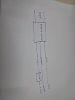
ThankyouSimple charge-pump converts -12V to positive 11V, light load. Supply and load both share the same ground.
Some rearranging allows a similar circuit to double +12V to +23 or 24V.
To build in real-life the SPDT switch can be a half-bridge as you choose.
By adding diode-capacitor stages you can obtain greater volt amplitudes.
View attachment 194639
Link below runs this schematic at website of Falstad's animated interactive simulator:
tinyurl.com/22amxgnb
Yes, as you said light load.Simple charge-pump converts -12V to positive 11V, light load.