Continue to Site

Welcome to EDAboard.com

Welcome to our site! EDAboard.com is an international Electronics Discussion Forum focused on EDA software, circuits, schematics, books, theory, papers, asic, pld, 8051, DSP, Network, RF, Analog Design, PCB, Service Manuals... and a whole lot more! To participate you need to register. Registration is free. Click here to register now.

Can we connect RC in Pic controller reset pin while programming through pickit 3 programmer

Status
Not open for further replies.

prakashvenugopal

Advanced Member level 1
Joined
Jun 1, 2011
Messages
473
Helped
15
Reputation
30
Reaction score
15
Trophy points
1,298
Activity points
4,973
Hi all,

I am trying to use the Pickit 3 programmer to Program my Pic device(16F785) (SOIC package)In system programming.

Controller MCLR --> Pickit 3 MCLR (1st pin)
Controller 5V VCC --> Pickit 3 VCC(2nd pin)
Controller Gnd --> Pickit 3 Gnd (3 pin)
Controller ICSPDAT --> Pickit 3 ICSPDAT (4th pin)
Controller ICSPCLK --> Pickit 3 ICSPCLK (5th pin)
--> (PIckt 3 6th pin is No connection)

My question is, can we connect RC in MCLR pin of the Microcontroller? 1k resistor to pull up to 5V and 0.1uf from mclr pin to gnd. ?
will it affect while programming the Pic microcontroller through pickit 3 programmer (during insystem programmming)
Kindly let us know.

Regards,
V. Prakash
 

Hi,

1k and 100n? Are these Microchip recommended values?
It just gives a tau of 100us.
Often the values depends on power supply and the used clock source. Please check datasheet.

If you want to stay with 1k and 100n, then add a 10k resistor to the RST pin. (From center of 1k/ 100n)

Klaus
 
Hi,

Thanks for the reply. I had checked the Pickit 3 user guide manual. Only Pull up resistor is recommended.
capacitor in the MCLR pin is not recommeded. Kindly refer the attachment.

I have to put rc in my reset pin to generate the reset during power ON and also i am doing insystem programming.
In such case what is the solution. kindly let us know.

Regards,
V. Prakash
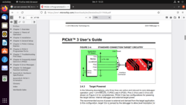
User guide link: https://ww1.microchip.com/downloads/en/DeviceDoc/51795B.pdf
 

Attachments

  • Screenshot from 2021-12-09 13-23-39.png
    Screenshot from 2021-12-09 13-23-39.png
    222.8 KB · Views: 251
  • Screenshot from 2021-12-09 13-23-48.png
    Screenshot from 2021-12-09 13-23-48.png
    241.5 KB · Views: 191

HI,

In such case what is the solution. kindly let us know.
In post#2 I recommended a 10k series resistor. What´s wrong with it?

***
I don´t think a tau of 100us brings much benefit.
I usually rely on true RESET ICs like MAX809.

Klaus
 
Keep your RC network if you need the delayed reset but isolate the MCLR pin from the RC junction with a resistor. MCLR is an input and it draws negligible current so the new resistor will have almost no effect on reset operation. Connect the Pickit directly to the PIC. During the programming cycle the MCLR pin has a signal on it that the capacitor will distort if it isn't isolated.

As stated earlier, the RC values you are using make no sense, 100nF is fine but 1K is far too low to create an appreciable delay, at least 10K is needed to be effective.

Brian.
 
Hi,

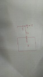
Ok. You are recommending to Put 10k instead of 1k with 0.1uf to have a tau of 1 msec? or
1k pullup with 0.1uf with series 10k resistor to MCLR pin of microcontroller. ? Kindly let us know.
kindly refer the image.

Regards,
V. Prakash
 

Attachments

  • IMG-20211209-WA0017.jpg
    IMG-20211209-WA0017.jpg
    27.4 KB · Views: 175

PICkit2 manual shows this circuit

1639039614508.png


3.2 ISOLATE VPP/MCLR/PORT PIN
When VPP voltage is applied, the application circuit needs to take into consideration that the typical VPP voltage is +12V. This may be an issue in the following situations:

If the VPP pin is used as a MCLR pin
The application circuit is typically connected to a pull up resistor/capacitor circuit, as recommended in the device data sheet. Care must be taken so that the VPP voltage slew rate is not slowed down and exceeds the rise time in the programming specification (typically 1 μs). If a supervisory circuit or a push button is interfaced to the MCLR pin, it is recommended that they be isolated from the VPP voltage by using a Schottky-type diode or limiting resistor as shown in Figure 3-1. For more information about using supervisory circuits with ICSP, see Application Note AN820 "System Supervisors in ICSP Architectures" (DS00820).

If the VPP pin is used as an I/O port pin
The application circuit that connects to the I/O pin may not be able to handle the +12V voltage. It is recommended to use a Schottky-type diode or limiting resistor as shown in Figure 3-1 to isolate the circuitry.
 

Hi,

Thanks for the circuit reference.

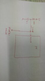
I am planning to use as attached schematic. Kindly let us know if any mistake.

Regards,
V.Prakash
Vetal / India
 

Attachments

  • IMG-20211209-WA0022.jpg
    IMG-20211209-WA0022.jpg
    28.2 KB · Views: 165

Hi,

Should work.

It´s exactly like recommended in the schematic of post#8. Why do you expect anybody to disagree?

Klaus
 

I expect your circuit to work. Previous comments also questioned the RC time constant and neccessity of a capacitor. In this regard, you should always refer to the MCLR behaviour of the specific component.

1639042248854.png


16F785 provides an internal MCLR noise filter, thus the capacitor is not required in most cases.
 

The capacitor is not there just for noise - it is also to slow down the rise of the \MCLR\ pin so that Vcc can reach it s full value before the reset is released.
I've not really found this necessary but ias it not harmful.
Susan
 

Status
Not open for further replies.

Similar threads

Part and Inventory Search

Welcome to EDABoard.com

Sponsor

Back
Top