Continue to Site

Welcome to EDAboard.com

Welcome to our site! EDAboard.com is an international Electronics Discussion Forum focused on EDA software, circuits, schematics, books, theory, papers, asic, pld, 8051, DSP, Network, RF, Analog Design, PCB, Service Manuals... and a whole lot more! To participate you need to register. Registration is free. Click here to register now.

Can I use only lower side of ir2110?

Status
Not open for further replies.

atifsheikh_91

Member level 1
Member level 1
Joined
Dec 28, 2011
Messages
38
Helped
0
Reputation
0
Reaction score
0
Trophy points
1,286
Activity points
1,566
Hello How can I use only the lower side of IR2110?

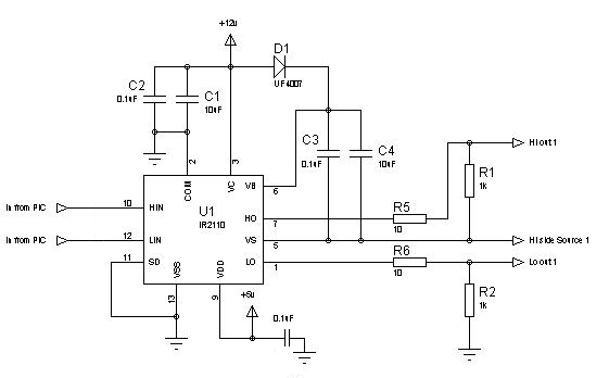
Please help me with circuits that interface PIC16f877a with ir2110.

what should be the value of VDD of IR2110 if the Power Rail of Transistors is 220VDC ? (in Half_bridge)
 

VDD should be the logic level of input. If its a MCU then VDD is +5V...For using higher side of ir2110 u should connect a bootstrap capacitor,, and that capacitor charges only during low side gate is on.

Hope this will be helpful. I had the same issue.
 

VDD should be the logic level of input. If its a MCU then VDD is +5V...For using higher side of ir2110 u should connect a bootstrap capacitor,, and that capacitor charges only during low side gate is on.

Hope this will be helpful. I had the same issue.


Can you make it more clearer?

---------- Post added at 20:19 ---------- Previous post was at 20:15 ----------

how to use only lower side?
 

When I used low side only, all I did was ignore the high side. Ground the high-side input. Connect the low-side input to the PIC. Connect VDD to +5V. Connect VCC to +AUX(the auxiliary voltage for driving the MOSFETs, eg +12V). Connect VSS to GND. Connect SD to GND. Connect COM to GND. LO goes to the MOSFET.

Take a look at the block diagram of the IR2110 (taken from the IR datasheet):

29_1327765776.png


You can see that the high-side and the low-side are pretty much independent.

Hope this helps.
Tahmid.
 
Last edited:
Connect COM to GND. HO goes to the MOSFET.


One more thing to ask ! what to do with VCC; wat should be its value if the power rail for h0bridge is 220VDC and how to calculate bootstrap cap. ?
 

You should have a +12V or +15V or some kind of auxiliary supply for driving the MOSFET. This is the voltage to be connected to VCC.

---------- Post added at 22:06 ---------- Previous post was at 22:05 ----------

Question:

Do you need to use only low-side or both high-side and low-side? You ask:
How can I use only the lower side of IR2110?
But later, you go on to ask:
what should be the value of VDD of IR2110 if the Power Rail of Transistors is 220VDC ? (in Half_bridge)

In a half-bridge converter, you would need to use both high-side and low-side drive.
 

You should have a +12V or +15V or some kind of auxiliary supply for driving the MOSFET. This is the voltage to be connected to VCC.

---------- Post added at 22:06 ---------- Previous post was at 22:05 ----------

Question:

Do you need to use only low-side or both high-side and low-side? You ask:

But later, you go on to ask:


In a half-bridge converter, you would need to use both high-side and low-side drive.

both questions are independent.
 

Ok. So, you got your answer for only low-side.
For both high-side and low-side, use this:


While there are formulae for calculating the value of the bootstrap capacitor, I find that these are often very difficult, if not impossible, to apply due to parameters such as capacitor leakage, etc. However, depending on the frequency and minimum and maximum duty cycles, an estimate may be made.

Hope this helps.
Tahmid.

---------- Post added at 22:25 ---------- Previous post was at 22:25 ----------

C1 and C4 may be polarized electrolytics as well.
 

Hello Tahmid,

Please, let me know advantages of using both low and high side instead of single driver as TLP250 or MC33153.
And, I would please you if you tell me where load and its supply are connected in your drawing of before.

Thanks!
 

Before this, you must know when to use a high-low side driver and when to use only low-side driver.

If you're going to be driving a full-bridge with positive bus voltage of 300VDC, then, you must use a dedicated high-low side driver. A single driver such as TLP250 is designed to drive MOSFETs configured as low-side switches with low voltage.

TLP250 is also designed to provide isolation while driving. However, it's slower than IR2110 and is designed to be used upto a maximum of 20kHz, whereas IR2110 can be used with frequencies higher than 100kHz.

You should read up a bit about high-low side drivers and why we need to use them, about high side configuration and low side configuration.

Hope this helps.
Tahmid.
 

Thanks for your help.

That's my question, when to use a high-low side driver and when to use only low-side driver. I could't find good informaton or books for the moment. That's why I am writing here.

I need to control a 48V / 3kW brushed dc motor without reverse (only one direction). I will use IGBT transistor and I think it will work between 4kHz and 20kHz. Also I plan to use isolator between microcontroller and IR2110. But I don't know the difference between double or single side configuration (except that high-low controlling is suitable for brake the motor, thing that I don't need).

Best regards.
 

High side switching is required when your MOSFET is in high side configuration. This is when the drain is connected to +ve and load is taken through source to ground. As a result source has no direct connection to ground. Here when +ve is 200v, your VGS has to be 200+10 = 210V because source is not directly connected to ground, and when on has a potential of 200v.
Low side is where load is taken from drain and source is connected to ground. Here, VGS is always eg 10v as source is connected directly to ground.

In bridge circuits you need both high and low side switching. The upper 2 switches need to be driven with high-side drivers and the lower 2 switches with low-side drivers. Drivers such as IR2110 come with facility for driving one high side and one low side (but can not be driven simultaneously, only alternately). Thus with 2 such drivers, you can drive a full-bridge. Or with one driver you can drive a half-bridge.

High-side driving in such chips is done using a diode-capacitor based bootstrapping technique. The MOSFET source is floating, so you need a voltage of about 10V greater than the source voltage. Example: Say your V+ is +12V. And your bootstrap diode has a Vf of 0.6v. In that case, when the capacitor is being charged, it is charged to (12-0.6) = 11.4V. When being discharged, there is 11.4v across the cap, and there is 12v on the line. So, voltage at source = 12V on load, and therefore, voltage on gate = (12+11.4) = 23.4V
This is more than 10V greater than your source voltage and therefore, you can successfully turn the MOSFET on in high side configuration.

Another method used is to generate an isolated gate drive voltage usually with a transformer.

If you have any other questions, feel free to ask.

Hope this helps.
Tahmid.
 
Now I understand operation with floating voltage in the high side.
What I still don't understand is advantages in use of half-bridge or single drive.
 

A single drive can output only one state. If the MOSFET is configured as high side switch, it can source current: output only +voltage and no output, but it can not output zero unless pulled down with a resistor. But using a pull-down would mean that you won't be able to get much current when output is zero. Same goes for MOSFET configured as low side switch, which can only sink current: output zero voltage. But it can not output +voltage unless a pull-up is used and if you use pull-up, you have the same problem in terms of current as pull-down.

Half-bridge or h-bridge, on the other hand, can generate both +ve and ground. If you use capacitor based half-bridge with a positive rail voltage of +12V, you can generate +6V or 0V with it. With an h-bridge or full-bridge, you can generate +12V or 0V. But with single drive, with high-side switch you can generate only +12V and with low-side switch, only 0V (without pull-ups or pull-downs).

Hope this helps.
Tahmid.
 

Ok Tahmid. I will try to buid the controller.
Thank you very much.
 

Single drive also has its advantage. If you want to drive DC motor and control speed and don't need to control direction, single drive is good enough. Plus, if you use a low-side switch, you won't need a high-side driver. Moreover, you'll require only one MOSFET/IGBT.
 
Actually I don't need to control direction. Anyway I will try both low side driver and high-low side driver and I will check performance.
Thanks for your help.
 

hi Tahmid
first sory for my englishyou said ' I work with only low side drive" I using %40 pwm duty irfp460 when I connect the ir2110 to circuit ir2110 its bust what problem gnd or Where should I use a zener. lin 5v and where connect to Vcc . can you check my desing D1 D5 and D8 where and What materials should I use

thans
a.JPG
 

Status
Not open for further replies.

Part and Inventory Search

Welcome to EDABoard.com

Sponsor

Back
Top