Continue to Site

Welcome to EDAboard.com

Welcome to our site! EDAboard.com is an international Electronics Discussion Forum focused on EDA software, circuits, schematics, books, theory, papers, asic, pld, 8051, DSP, Network, RF, Analog Design, PCB, Service Manuals... and a whole lot more! To participate you need to register. Registration is free. Click here to register now.

Can any one help me out to find out the reason for RS 485 IC burning reasons ?

Status
Not open for further replies.

prakash12346

Newbie level 5
Newbie level 5
Joined
Nov 15, 2014
Messages
10
Helped
0
Reputation
0
Reaction score
0
Trophy points
1
Activity points
76
We have a circuit which master RS 485 module is designed as fail safe mode and (DC GND) connected directly to Earth. It communicates to other RS 485 modules in daisy chain connection with/ with out end node termination & this modules are connected (DC GND) to earth via a RC in parallel network ( 100 R, 0.1 uf) . Now the 485 chip in master module is getting burnt after some days of communication. Can any one help me out what will be the issue. Whether earth is creating issue and if yes why it is.

Design attached for referenceView attachment case 4.pdfView attachment case 5.pdf.
 

Where you are installing this system? what is the environmental condition? What is the part number of that TVS diode? Why you are connection DC ground to the mains earth? Why there is no RC network for master while others have?
 
Kindly explain what you mean by "Earth", especially w.r.t the chips power supply GND point.

Chips getting burnt are obviously caused by too large a current flowing somewhere. Large currents are produced when there is no clear understanding of voltage levels in a system.

Is the Earth of one system at the same potential as the Earth of all other systems ?
Your name suggests you are possibly based in India, so these questions are very relevant and require attention.
 
Consider ESD damage thru ground spikes causing input signals to exceed supply rails can occur in nanosecond speeds. Then re-evaluate. Consider raising CM impedance with chokes.


There is no document showing capacitive coupling of all independent DC supplies and ground connections. Ignore AC isolation and assume there is capacitive coupling on transformers.
try to draw for us or show.
 
Where you are installing this system? what is the environmental condition? What is the part number of that TVS diode? Why you are connection DC ground to the mains earth? Why there is no RC network for master while others have?

Thank you so much for your reply. We are installing system in big apartments which is under construction. Environment condition with be 30 to 40 deg celsius & 60 to 70 % humidity. Part no is . DC ground to earth is to take care of EMC for RF signals for RC in parallel. Direct connection is happening through metal enclosure. Module 1 is master. Master has but slave does not in one config. Option for termination is provided in module but site engineer has missed that in one of cases. Waiting for your reply
 

Where you are installing this system? what is the environmental condition? What is the part number of that TVS diode? Why you are connection DC ground to the mains earth? Why there is no RC network for master while others have?

Sorry part no is TPD2E007DCKR2

- - - Updated - - -

Kindly explain what you mean by "Earth", especially w.r.t the chips power supply GND point.

Chips getting burnt are obviously caused by too large a current flowing somewhere. Large currents are produced when there is no clear understanding of voltage levels in a system.

Is the Earth of one system at the same potential as the Earth of all other systems ?
Your name suggests you are possibly based in India, so these questions are very relevant and require attention.

Thanks for your reply. No it is normal electrical EARTH and it connected to Power supply GND point
Can you explain me or give hint where the voltage level has no clear understanding so it will be better for my debugging
Yes. All Earth is common. But Power supply Ground's are different.
Yes I am from India. Thank you once again. Expecting your support to find the root cause.
 

You should only terminate the cable at the two ends, not at modules in the middle.

The most likely cause of your problem is the ground connection as others have pointed out. RS485 works on the principle that the polarity of voltage across the wires is swapped to send a '0' or '1' bit and the receiver (slave) units check which wire has the higher voltage to know what the bit was. Although it is the polarity that carries the data, there is also a limit to how much voltage you can apply across the wires and also from each wire to the ground at each interface. I strongly suspect your problem is that the grounds at each unit are either at different potentials and the maximim voltage is being exceeded, or, spikes of interference along the ground path are momentarily exceeding the voltage limit.

Are you running a signal ground wire between the units as well as the data wires? I mean a direct link wire and not a connection through building grounds.

Brian.

Sorry Mr. Brain for late reply. Yes we are running a signal ground which has terminated with 100 ohms resistors to DC ground.

Secondly i faced one more issue recently. The protection diode was not there for A & B of 485 chip. The environment was clean and we found the chip is blew away. what might the cause. If we run AC voltages near CAT 5 cable whether that will cause those problems?
 

It's Brian not Brain - there's lots of Brian in me but not a lot of brain.

The terminating resistors go across the signal wires, not from each to ground. You only need them at physical each end of the wires, where there are other modules connected along the way, they should not be terminated.

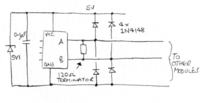
I still think the ground is the problem. Especially in apartments where it is quite likely that spikes of Earth current flow though the mains AC supply wiring as appliances are connected and disconnected. It only takes a microsecond to kill one of those ICs. I would short out all the resistors in the ground wire between the ICs, they should all share a direct ground connection with each other. If you want to add protection, use a pair of normal silicon signal diodes on each signal wire, from ground to VCC and also add a Zener across the supply to dump any excess voltage.

In one of your diagrams you show additional resistors, one from each signal wire to ground or VCC. That is good practice because it sets undriven lines to a known logic state but, you do it at both ends of the wires. It should only be done at one end.

If you feel the need to add additional Earth connections, I would be inclined to connect Earth and ground directly together but only at one end, preferably the master end. If you connect additional Earth/ground points you bring back the risk of there being a voltage drop between them and unwanted currents flowing along the ground wire.

You should keep AC power wiring and CAT-5 spaced apart to minimize coupling between them. I Europe this is normally done by passing them through plastic trunking with a built-in divider to prevent them touching. I'm not sure if it's a legal requirement or not and it may not apply in your country.


Brian.
 
I agree with the comments given by Brian.

I feel the 100 ohm resistor getting in series with all the modules and master is causing the 'ground lift' which is affecting the signal levels at different ICs in different modules. That's why some ICs are going into fumes ...
Immediately you have to take out and have a short in place for this 100 ohm resistor at each of connector pin # 1.
Having an opto-isolator for all the modules would also help in overcoming such situations.
 
Hi all
I have encountered the problem again after removing the DC ground to earth connectivity. I will put my observations at time of failure
1. The IC case( die) is getting heated up initially.
2. Gradually the the temperature is rising up and blows up the IC but even the IC is functioning.
3. After some time say 1 day the function of IC stops.
This is happening when we communicate through the IC in time period of 50ms

Can you put your views and help me out to figure it out the root cause
 

You MUST have ground conductivity. The data is sent by reversing the polarity across the data wires but they both have to be withing the allowed voltage range. If you remove the ground it is quite likely that you have exceeded that range.

Example with ground:
TX+ = +2V at both ends
TX- = +4V at both ends
The difference is 2V which is OK and the voltages are within limits.

Example without ground
TX+ = +30V
TX- = +32V
The difference is still 2V but both voltages are high enough to cause damage.

Brian.
 

Hi,

just to be sure: there should be only two terminating resistors (one at each end of line).

If you have a spare wire in your cable you could try to connect it as common GND. Then the connections to earth should be with resistors and/or varistors. (maybe try 100R, or try 1000R)

****
Is ist possible that your EARTH wires (the ones installed in the house) are carrying current (as PEN)? then a voltage drop is quite usual. And the use of common GND may bring problems.

To validate "EARTH" voltage you could use a high ohmic DVM and measure the voltage between each devices EARTH connection and a metal pipe (drink water, heating pipe, gas pipe).
Always test AC and DC separately. If you see voltages more than 5V AC or DC you can´t rely on this EARTH voltage. Then you need another solution for common grounding your devices.

If you expect sporadic voltage spikes on EARTH wires, then use a scope to test voltage referenced to the metal pipes.

Good luck

Klaus
 

You MUST have ground conductivity. The data is sent by reversing the polarity across the data wires but they both have to be withing the allowed voltage range. If you remove the ground it is quite likely that you have exceeded that range.

Example with ground:
TX+ = +2V at both ends
TX- = +4V at both ends
The difference is 2V which is OK and the voltages are within limits.

Example without ground
TX+ = +30V
TX- = +32V
The difference is still 2V but both voltages are high enough to cause damage.

Brian.

Hi Brian

I have connected third wire to DC ground. Only i have removed the DC ground shorting the Earth. Pl find the voltage and current measured and wiring diagram how the devices are connected.

Hi,

just to be sure: there should be only two terminating resistors (one at each end of line).

If you have a spare wire in your cable you could try to connect it as common GND. Then the connections to earth should be with resistors and/or varistors. (maybe try 100R, or try 1000R)

****
Is ist possible that your EARTH wires (the ones installed in the house) are carrying current (as PEN)? then a voltage drop is quite usual. And the use of common GND may bring problems.

To validate "EARTH" voltage you could use a high ohmic DVM and measure the voltage between each devices EARTH connection and a metal pipe (drink water, heating pipe, gas pipe).
Always test AC and DC separately. If you see voltages more than 5V AC or DC you can´t rely on this EARTH voltage. Then you need another solution for common grounding your devices.

If you expect sporadic voltage spikes on EARTH wires, then use a scope to test voltage referenced to the metal pipes.

Good luck

Klaus

Hi Klaus

I have attached the voltage/ current analysis and wiring of modules. Pl comment

Supplier RCA just arrived. He closed as EOS
 

Attachments

  • RS 485 CIRCUIT-2.pdf
    41.4 KB · Views: 352
  • RS 485 IC Voltage Analysis-1.pdf
    144.2 KB · Views: 236
Last edited by a moderator:

I'm not sure I understand the ground wiring. What you should have is pin 5 of ALL the ICs joined directly together. On your schematic you show a ground symbol on them all which implies they are joined to ground but then you also have a network of 100 Ohm resisitors grounded at both ends which means they do nothing.

I suggest you remove all the 100 Ohm resistors except one at the master IC and connect that between pin 5 and your building ground. It is essential that all the pin 5 connections are at similar potential or the data line voltages may go beyond their limit.

Brian.
 

Hi,

To your schematic.
* the databus (A and B) should be straight inline (no star connection). at both ends of the bus you should install termination resistors.
* A and B needs to be a twisted pair line with a wave impedance of 120 Ohms (nominally)

* do all your slaves have independent (galvanic isolation) power supplies?
* i recommend to use protection circuit to protect each ADM485. Maybe a BAT54S (anode to GND, center to A (B respectively), cathode to VCC) is sufficient.
* use a 10uF tantalum and a 100nF X7R next to VCC and GND pins of ADM.
* With your circuit, there should be about no GND current between devices. ( R13, R37...)
* only one device must be active (driver) one time
* all devices must be properly powered all the time.

Your measurement:
!!! I see a problem with the voltages. Differential voltage in TRANSMIT mode must be >1.5V. even with 27 Ohms load. But in your circuit it is max. 0.9V. This is too low.
There should be no difference of the signal voltages (A and B) wether you are in "idle" mode or "receiver" mode. This enables only the receiver´s TTL output "RO".
!!! In either case |differential_voltage| must be >0.2V, But this isn´t the case in your measurement.
!!! in case of "idle" or "receive" the |D+_current| as well as |D-_current| must be below 0.4mA. This is not the case with your measurement.

Strange measurement values. Please check.

Klaus


Read application note: https://www.analog.com/media/en/technical-documentation/application-notes/AN-960.pdf


Hi

Thanks for your inputs. My answers

1. The modules are connected in Daisy chain. To simulate in orcad we done like this.
2. Both Ends we are terminating 120 ohms
3. Yes Slave modules has independent power supplies and that ground is connected to Master ground using 100 ohm resistance. No galvanic isolation is provided.
4. We are using SP 485EE in our modules( To simulate only we got ADM485 so we used only for simulation purpose). Here there is a difference from manufacturer. Exar SP 485 does not have thermal shutdown where other manufacturers like Analog, Maxim, TI has.
5. Can you draw me a circuit for adding capacitors as you suggested.It will be so useful for me.
6. We done the measurement by connecting 13 slaves to Master and measured at master A, B & Ground. I will conduct the readings once again.

If any other things i need to try pl let me know it will be very helpful for me.
 

Status
Not open for further replies.

Part and Inventory Search

Welcome to EDABoard.com

Sponsor

Back
Top