umery2k75
Advanced Member level 1

There are 10 absorption chiller and 1 controller(D.D.C=Direct digital controller) to control them. The system has been installed and tested of it's functionality two years ago.The communication method is CAN 2.0. The problem is that once, the DDC is programmed to store the 10 nodes address, it must not forget the address, until it's battery drains out. One by one, the DDC appears to forget the chiller's address or forget the total 10 nodes addresses. The chiller goes OFFLINE and cooling stops. These days, they have bypassed the DDC and chillers are working manually.
Recently, I came to know about the problem. I was fascinated and willing to discover the reason behind it. The correspondence with the manufacturer has gone for about 1.5 years in keeping in view the same problem. The manufacturer had sent the new cable, sent the new controller and everything has been replaced, still the problem remains. The manufacturer is not willing to sent their engineers, due to security reason of the country.When I first went over their, I saw this.
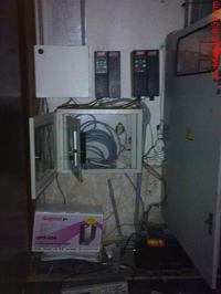
The middle box is the controller and the two upper black units are the inverters DANFOSS VLT2800 and the left panel is a digital controller with some relays. My first attempt was that I asked them to move this controller away from the inverter. These two inverters has 4.5KHz modulating frequency, I was afraid that this could be causing the RAM of the controller to flash out. Sometimes all the address of the controller goes off, or they goes off one by one.I was not trying to ZOOM IN, to solve the problem, just trying to solve by means of common practices. I had moved this unit away from everything and even put the metal sheet everywhere, so interference could not affect it. The picture of the controller are
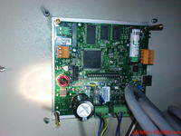
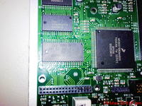
The 160 pins is the controller. The IC in which AMD is written is the flash. The upper two are the RAM. I have seen it's datasheet
Controller=MC68376BGMAB20
Flash=AM29F800BB
2 RAM=R1LP0408CSP-5S1
I don't have the picture of absorbtion chiller unit electronic controller.It looks like this

and the unit looks like this
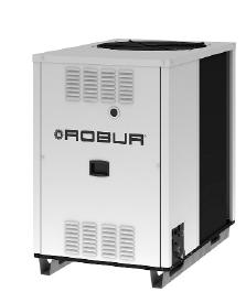
It has Motorola Controller. The number is DSP56F807PY80
Summarizing, the above details. The problem is their for over 2 years. The person who do installation has done installation in many places and he's an experienced person. This house, only has problem. Every electronic equipment has been replaced, except the chiller unit electronic boards. My guess is that either, the DDC forget the node address or chiller unit forget it's own address.In both condition, the chiller goes offline. There's no symmetry. Any 1 unit out of 10 units can go offline. It might occur, that the DDC remember the address for over 1 week. Sometimes after a few hours, the nodes address got lost. Sometime after 2 days, the DDC forget the address. Maximum period is of 1 week. It's like one by one, or altogether the units goes off in a period of time.Nobody can guess, which units will go offline and at what time. I have seen JTAG ports on the DDC and absorption chiller unit. I have wrote to the manufacturer, but still there's no response. I'm interested to see where the addresses of the chiller unit are stored in RAM. I will monitor that data register. There are also CAN Bus tester, analyser in the market. Are they helpful? I also want to make sure, the terminating point resistance must be 120ohm.
Please suggest what to do.
Recently, I came to know about the problem. I was fascinated and willing to discover the reason behind it. The correspondence with the manufacturer has gone for about 1.5 years in keeping in view the same problem. The manufacturer had sent the new cable, sent the new controller and everything has been replaced, still the problem remains. The manufacturer is not willing to sent their engineers, due to security reason of the country.When I first went over their, I saw this.

The middle box is the controller and the two upper black units are the inverters DANFOSS VLT2800 and the left panel is a digital controller with some relays. My first attempt was that I asked them to move this controller away from the inverter. These two inverters has 4.5KHz modulating frequency, I was afraid that this could be causing the RAM of the controller to flash out. Sometimes all the address of the controller goes off, or they goes off one by one.I was not trying to ZOOM IN, to solve the problem, just trying to solve by means of common practices. I had moved this unit away from everything and even put the metal sheet everywhere, so interference could not affect it. The picture of the controller are


The 160 pins is the controller. The IC in which AMD is written is the flash. The upper two are the RAM. I have seen it's datasheet
Controller=MC68376BGMAB20
Flash=AM29F800BB
2 RAM=R1LP0408CSP-5S1
I don't have the picture of absorbtion chiller unit electronic controller.It looks like this

and the unit looks like this

It has Motorola Controller. The number is DSP56F807PY80
Summarizing, the above details. The problem is their for over 2 years. The person who do installation has done installation in many places and he's an experienced person. This house, only has problem. Every electronic equipment has been replaced, except the chiller unit electronic boards. My guess is that either, the DDC forget the node address or chiller unit forget it's own address.In both condition, the chiller goes offline. There's no symmetry. Any 1 unit out of 10 units can go offline. It might occur, that the DDC remember the address for over 1 week. Sometimes after a few hours, the nodes address got lost. Sometime after 2 days, the DDC forget the address. Maximum period is of 1 week. It's like one by one, or altogether the units goes off in a period of time.Nobody can guess, which units will go offline and at what time. I have seen JTAG ports on the DDC and absorption chiller unit. I have wrote to the manufacturer, but still there's no response. I'm interested to see where the addresses of the chiller unit are stored in RAM. I will monitor that data register. There are also CAN Bus tester, analyser in the market. Are they helpful? I also want to make sure, the terminating point resistance must be 120ohm.
Please suggest what to do.
