Vermes
Advanced Member level 4

Assumptions:
Accuracy up to 0,01mm pitch. Simplicity in use and eliminating human error.
Mechanics:
In the first form of the device, it consisted of:
- unipolar stepper motor 0,9 degree/step, responsible for setting the piston stroke
- steel stem attached to the screw, which changed the rotary motion of the motor into the shaft sliding motion
- “table”, where the injector for calibration can be mounted
- bulb, which lights at the moment of contact of the steel connector of the shaft and injector plunger
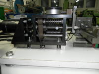
Calibration was based on the fact that the reference point (up to a bulb lights) is set on mounted injector, and then enable the injector, so that the plunger was attached by the coil (open the injector), then the controller moved the pin by the desired piston stroke and the adjusting screw was screwed (adjusting screw pushed the plunger forward) until the light bulb turns on. At the end, the lock nut was screwed. That method was very inaccurate. This is why you should assembly a controller which fully calibrate the injector.
Elements of the calibrator:
- 16-key keyboard on two 8-bit expanders cooperating with the controller on the I2C bus
- executive module of two unipolar stepper motors on I2C bus
- motherboard of main controller
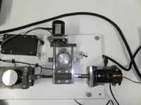
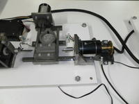
The device was developed by two stepper motors, where one of them was responsible for moving the table on which there was an injector (you have to move the table for this reason that the screw turning the rotational movement to the sliding is only about 15-20mm long and is not sufficient to catch the reference point). The screw was made specifically for this device, it is an hardened screw, finely rolled. The immobilization of the table was gained by the electromagnet. The second motor is responsible for the tightening the adjusting screw. Picture below shows the device after the development of two unipolar stepper motors 0,9 degree/step.
If you gain a small accuracy, it may consist of a few mechanical errors:
- motor of the adjusting screw can be retained electronically for the time of tightening the lock nut. Due to the high accuracy of the motors, their power is small, so it can happen to move the engine head while tightening
- steel pin can “stick” to the piston after running the injector, due to its magnetic properties. Due to the magnetic effect, poor sequence of performed calibration operations
- non-symmetrical introduction of the stem (no insulation of the side wall) into the injector led to contact with the wall of the injector nozzle
Power supply:
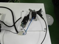
The picture shows the power supplies of the device.
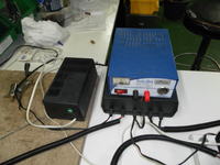
The device is powered from three separate power supplies. The first one on the left side of the photo with the green switch is a stepper motor power supply. The second big in housing Z-17 is responsible for power the drivers, the injector and electromagnets. The power supply was built on a symmetrical dual transformer 50W with voltages on the secondary windings: 2x6,5V and 2x15V. One of the detaches 6,5V is responsible for regulated power supply PWM of the injector in the range of 0-7,5V DC. The injector in the car is not DC powered, but pulse from the injection controller, so the injector supply voltage 12V DC leads to its rapid heating. Therefore, in order to slow the rise of the temperature of coil, the voltage is so low. The lower voltage, the plunger must be located closer to the coil. The smaller voltage , the less current flows through the windings, which leads to slower heating of the winding.
The second detach 6,5V controls the drivers.
The first detach 15V powers the electromagnets. Due to the fact that the actuator requires 12V and 4A, the transformer was not able to provide such an amount of energy, to power the actuator the blue power supply is used 12V 50W, but the control is on the main power supply.
Electronics:
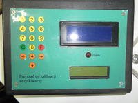
The front panel of the driver:
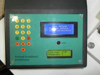
The diodes informs if the pin connects with the injector plunger.
The driver still is responsible for determining the piston stroke. The driver has a 6-keys keyboard with derived connector kk2 6P with the green LCD display 16x2 characters and was connected through this connector to the main controller. In the menu there is an option that allows full control over the driver. Keys responsible for the control are 4 directional arrows, CANCEL, ENTER and “0” key. The are responsible for navigating the menu, CANCEL for cancellation of changes, “0” for approval of changes and entry in the EEPROM memory of the driver, ENTER for approval, entry into memory and leave the operating menu of the driver.
The main driver:
The display of the driver is a 20x4 character LCD display, white negative.
Functions:
- setting of the injection voltage in the range of 0-7,5V
- full configuration of unipolar stepper motors
- choosing of the order of the windings
- setting the time between pulses for minimum and maximum speed
- 10 speed levels after defining the pulses
- selection of working full-step or half-step
- independent setting the numbers of “blind spot” steps for the engine responsible for the piston stroke as well as responsible for the adjusting screw
To eliminate vibrations at the connector, engines after receiving information from the sensor still make an additional number of steps to increase the contact surface.
All the settings (except those in the driver that determines the piston stroke, because it stores its settings inside the microcontroller) are stored in the external EEPROM, so they can always be replaced after exceeding number of records and load the settings into the new bone.
Protection:
The calibrator is equipped with limit switches to avoid collision of the table with stem mount. The brake was also equipped with a limit switch, so that it is not possible to calibrate the injection with the brake on. When the brake is on, and you want to perform the calibration, the display shows the message about the brake and it should be turned off by pressing the ENTER key.
The program also features a watchdog in case of crashes or other anomalies.
The calibrator has an additional protection, which was the reason why the settings had to be transferred to an external EEPROM memory. Before each calibration, the flag is set and saved to memory, and after the calibration, the flag is reset and its value is also written to memory. Thus, if during the calibration any error occurs in the program or power failure occurs, or anything else interfere with the calibration, before re-calibration there will be displayed an error message and the re-preparation of the injector message and the procedure will start once again from scratch. The message is to be continued, until you press the ENTER key.
Aims achieved:
- the accuracy of <0,01mm
- human error eliminated
- simplicity of use
- high accuracy and repeatability
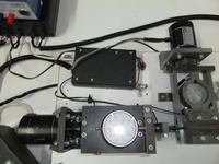
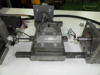
Link to original thread (useful attachment) – Kalibrator wtryskiwaczy do samochodowej instalacji gazowej.