Fovakis
Member level 5

- Joined
- Nov 15, 2012
- Messages
- 88
- Helped
- 1
- Reputation
- 2
- Reaction score
- 1
- Trophy points
- 1,288
- Location
- Greece,Athens
- Activity points
- 2,028


Rinput is infinite. Routput is infinite. If you are asking for IMPEDANCE, that's different. What's your frequency?
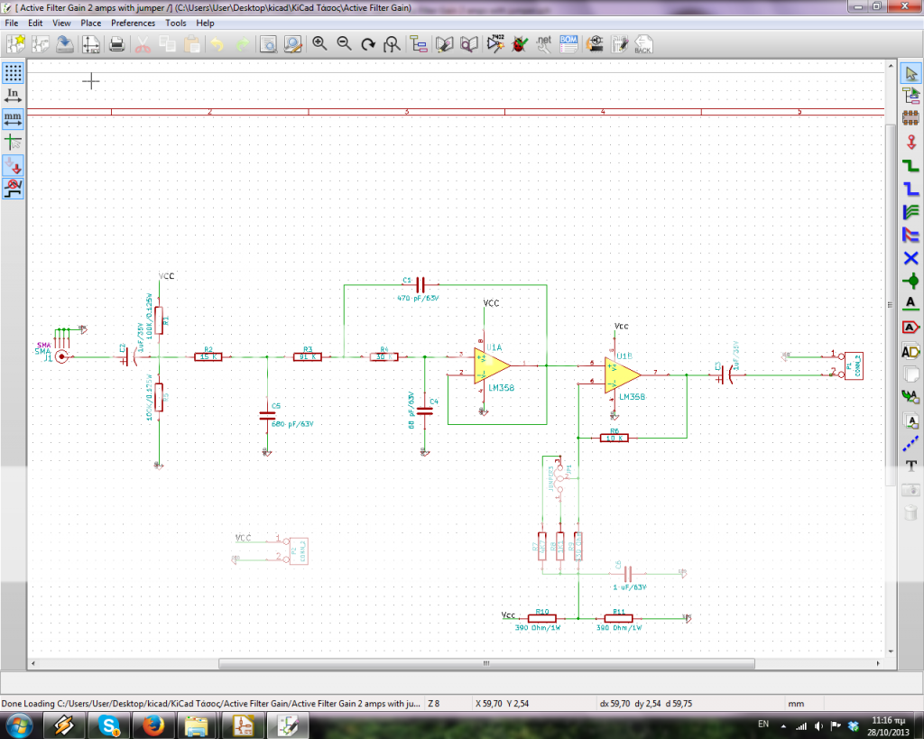
Assuming the input and output capacitors have negligible impedance at the filter frequency of interest then the output impedance is basically the op amp output resistance (as defined in the data sheet) divided by the loop gain (open loop gain minus the closed-loop gain) at the frequency of interest. The exact input impedance is a complex function of the input resistors and capacitors plus the feedback through C1. It's most easily determined using a Spice simulator.
The Sallen-Key lowpass filter has a voltage gain of 1 (like a piece of wire) at frequencies below its cutoff frequency. Its power gain does not matter.
The amplifier following the filter opamp has a voltage gain of (I can't read the tiny pastel sideways resistor values).
Why do you need to calculate Zin? Is this a school mathamatics exercise or is it a simple electronic circuit?
The filter circuit MUST be fed from a low impedance like the output of an opamp.
I still cannot read your tiny schematic with pastel sideways numbers on it and ads all over the page. Increase its contrast and post it HERE attached to your reply instead of posting it over at Photobucket.
- - - Updated - - -
Your output opamp is WRONG:
Then the low impedance mixer can directly drive this filter.Before this filter there is a double balanced ring diode mixer that downconvert a signal of 30MHz to a baseband. The mixer's output (ideally) is 50ohm.
The power gain has nothing to do with Zinput and Zoutput. The output power is Vout (from the opamp) squared/Rload. But there is no load.i don't know the Zinput and Zoutput to convert the voltage gain=20log(Vout/Vin) to power gain. I need to know what is the Zout and Zin.
Shame on Texas Instruments and shame on Cornell Edu for copying it. It is very wrong. See my corrections to it:Why this voltage divider is wrong?
Then the low impedance mixer can directly drive this filter.
The power gain has nothing to do with Zinput and Zoutput. The output power is Vout (from the opamp) squared/Rload. But there is no load.
Power gain is normally used for RF fixed impedance lines which are typically 50 ohms. The op amp is operating at low frequency with a relatively high input and output load impedance. So you use voltage gain, not power gain, for the filter. Voltage gain is typically used for low frequency circuits. Calculating power gain for such a circuit makes no sense.
It definitely makes no sense in this place, because there's no impedance matching involved.But when you have a receiver chain you want to calculate the Power Gain of total chain.
But it is. Fortunately it's meaningless regarding receiver performance.So the end i will have a Zout/Zin which is a complex number.i don't want something like this
I undertand what you are telling to me..but. If i want to write down "the Total Gain of my Receiver".what can i do for this? Please, enter in google "Receiver Architectures - Springer" it is a pdf 44 pages with Title Chapter 2 Receiver Architectures. Go on chapter 2.6 page 37 to 39.It definitely makes no sense in this place, because there's no impedance matching involved.
So swamp the input with a resistor.....
However, your filter design is going to be all kinds of noisy (resistor thermal noise), as it has 15K in series with the input which sets the minimum impedance it presents to the mixer, get that down to something more reasonable.
Your diode ring mixers IMD performance will be strongly influenced by its terminating impedance anyway, so you need to do something about that gross mismatch for both noise and intercept reasons.
If I was designing a simple rx like this I would probably follow the mixer with a diplexer going over as low as I could find suitable magnetics for (maybe a Mhz or so), with the high pass leg terminated into a 50 ohm resistor. This takes care of the termination at high frequency, and the low frequency leg feeding a common base amplifier to isolate the mixer from the following filter (And to transform the impedances).
I would also suggest that MFB filters are usually better behaved then sallen & key in this sort of application.
I recommend "Experimental methods in RF design" for your reading pleasure.
HTH.
Regards, Dan.
I guess it won't be needed. We would firstly ask if the AF output needs termination at all. Secondly if a low impedance termination has any AF SNR impact. Only if the answer is true in both cases, the effort actually pays.If I was designing a simple rx like this I would probably follow the mixer with a diplexer going over as low as I could find suitable magnetics for (maybe a Mhz or so), with the high pass leg terminated into a 50 ohm resistor. This takes care of the termination at high frequency, and the low frequency leg feeding a common base amplifier to isolate the mixer from the following filter (And to transform the impedances).
Now you could match this by using a transformer to step the 50 ohms from the mixer up to 12K
a common base stage with the collector load being a transformer into the filter would be how I would be thinking at that point and is about as simple as it gets.
We use cookies and similar technologies for the following purposes:
Do you accept cookies and these technologies?
We use cookies and similar technologies for the following purposes:
Do you accept cookies and these technologies?
