[SOLVED] Calculate MOSFET Rating
- Thread starter ismu
- Start date
- Status
- Not open for further replies.
vimalkhanna
Full Member level 6

The power current needed is 24V/80amps for 2000watts power .
.A full wave bridge can be designed using sets of four Mosfets with transformer primary driven by the bridge and having a rating of 100amps .
The loss in the switching needs to be less than 5% of this and such data means raings of the switches has to be 200amps .
As such STB300NH02 can be used which is rated at 24V and has 120amps as the Id .
This has an Rdon of 12mohm. and very low powerloss occurs ..

ismu
Full Member level 2

STB300NH02 is 24v . But at charging time battery may take 29v for full charge cutt , can this damage MOSFET ?
Can you give a complete calculation for full bridge sine wave mosfet rating for any watts with example .Expecting your replay")
Can you give a complete calculation for full bridge sine wave mosfet rating for any watts with example .Expecting your replay

mister_rf
Advanced Member level 5

Yoy don’t need to start from scratch, read those topic first:
https://www.edaboard.com/threads/195822/
https://www.edaboard.com/threads/96053/
and later you may decide the best solution for changing from 12V to a 24V power supply.
https://www.edaboard.com/threads/195822/
https://www.edaboard.com/threads/96053/
and later you may decide the best solution for changing from 12V to a 24V power supply.
vimalkhanna
Full Member level 6
The pure sine drive is given by the controller drive ,,,how do you handle the power to deliver 2000watts ..??
means 100amps currents at 29VDC
means 100amps currents at 29VDC

Tahmid
Advanced Member level 6
- Joined
- Jun 17, 2008
- Messages
- 4,764
- Helped
- 1,799
- Reputation
- 3,590
- Reaction score
- 1,663
- Trophy points
- 1,413
- Location
- Berkeley, California
- Activity points
- 30,739
I want to make 2kw inverter at 24 volt battery and 50hz freq: using sine wave PWM technique.
How can i calculate current through MOSFET and voltage ,watts ,and which type mosfet can i use, how many numbers ? Please help me
This has been explained here: https://www.edaboard.com/threads/253455/#post1086327
ismu
Full Member level 2
Mr .Tahmid ,i can see you replay from https://www.edaboard.com/threads/253455/#post1086327
please clarify my doubts:
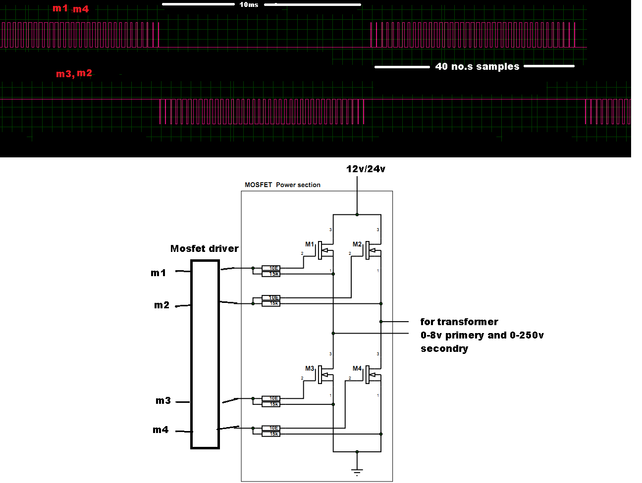
1--Can you xplain about how can i find inverter efficiency (75%) if i am using bridge type sine wave at 50hz freq and each cycle
has 40 no of samples for PWM(refer image)
2--What you mean by push pull converter is it same as full bridge? why 1.5 is used?
3--i think u got mistake in loss calculation: 30x30xRdson is this correct?
Can you give an example calculation for 2KW load at 24v and for full bridge type (see pic)
Waiting for your replay

please clarify my doubts:
1--Can you xplain about how can i find inverter efficiency (75%) if i am using bridge type sine wave at 50hz freq and each cycle
has 40 no of samples for PWM(refer image)
2--What you mean by push pull converter is it same as full bridge? why 1.5 is used?
3--i think u got mistake in loss calculation: 30x30xRdson is this correct?
Can you give an example calculation for 2KW load at 24v and for full bridge type (see pic)
Waiting for your replay
Attachments
Tahmid
Advanced Member level 6
- Joined
- Jun 17, 2008
- Messages
- 4,764
- Helped
- 1,799
- Reputation
- 3,590
- Reaction score
- 1,663
- Trophy points
- 1,413
- Location
- Berkeley, California
- Activity points
- 30,739
Mr .Tahmid ,i can see you replay from https://www.edaboard.com/threads/253455/#post1086327
please clarify my doubts:
1--Can you xplain about how can i find inverter efficiency (75%) if i am using bridge type sine wave at 50hz freq and each cycle
has 40 no of samples for PWM(refer image)
2--What you mean by push pull converter is it same as full bridge? why 1.5 is used?
3--i think u got mistake in loss calculation: 30x30xRdson is this correct?
Can you give an example calculation for 2KW load at 24v and for full bridge type (see pic)
Waiting for your replay
1) To get the exact value of the efficiency, you would need to measure the input power and output power and calculate: efficiency = ouput power / input power
75% was just an assumption that I made. Usually, you may find that the efficiency varies between 70% to 90%.
2) I was referring to the 2-transistor push-pull converter: https://en.wikipedia.org/wiki/Push–pull_converter
1.5 is because, in a push-pull converter, the peak current is roughly 1.5 times the average current. It's also 1.5 for full-bridge converter.
3) No, it's 20A. 30A is the peak current. But 20A is the average current. We're considering the average power loss which is calculated using the average current.
Hope this helps.
Tahmid.
ismu
Full Member level 2
thanks tahmid.
1-- i can calculate 4x4(full bridge)=16 mosfet 80NF55 in 24v 2000w inverter . is this currect?
2-- i can see pulsed current is 320A , actually sine waves are pulsed(PWM) then y don't take 320A in calculation?
3-- for this 2000w inverter can i Load induction cooker(1800W). i tried this but MOSFET(80NF55 16nos for bridge) damaged and its cannnot working even 2sec. why?
waiting your replay.
Tahmid
Advanced Member level 6
- Joined
- Jun 17, 2008
- Messages
- 4,764
- Helped
- 1,799
- Reputation
- 3,590
- Reaction score
- 1,663
- Trophy points
- 1,413
- Location
- Berkeley, California
- Activity points
- 30,739
So, we're assuming 2kW maximum power.
1) This seems fine.
2) The pulse current is for a pulse of very short width, very small duty cycle. Better use continuous rating.
3) Did you measure the current the cooker draws? Maybe, during startup, it draws too much current, damaging the MOSFETs. See if you can add a little "soft-start" to the inverter.
Hope this helps.
Tahmid.
Tahmid
Advanced Member level 6
- Joined
- Jun 17, 2008
- Messages
- 4,764
- Helped
- 1,799
- Reputation
- 3,590
- Reaction score
- 1,663
- Trophy points
- 1,413
- Location
- Berkeley, California
- Activity points
- 30,739
I can not tell the exact value, but it's very small. Sometimes in other datasheets, I have seen a value of 2% stated. So, this value (320A) can not be used.
- Status
- Not open for further replies.