Continue to Site

Welcome to EDAboard.com

Welcome to our site! EDAboard.com is an international Electronics Discussion Forum focused on EDA software, circuits, schematics, books, theory, papers, asic, pld, 8051, DSP, Network, RF, Analog Design, PCB, Service Manuals... and a whole lot more! To participate you need to register. Registration is free. Click here to register now.

[PIC] Bypass PIC24FJ128GA306

IntronDSOs

Newbie level 4
Newbie level 4
Joined
Aug 5, 2021
Messages
6
Helped
0
Reputation
0
Reaction score
0
Trophy points
1
Activity points
49
I woud like to dump the firmware from an PIC24FJ128GA306, i use a PICKIT4, but the PIC is protected and i cant read out. Configbit Security is set and JTAG is disabled.
MPLAB X IDE and IPE print : Warning: Debug bit is set on target image. This may not run correctly in production.

Is there a way to bypass the Security bits or is there any glitch (fault injection) possible?
 
I doubt that there are few if any members here that will help.

If you are located where the laws of the USA apply defeating any security protecting intellectual property (IP) is in fact a crime. See the Digital Millennium Copyright Act (DMCA). Describing how to do this is a constitutionally protected right, but actually doing it to access IP that you have no rights to is not.

Perhaps there are members here that can help but it's too much of a risk for me.

And yes, there are ways to defeat the Microchip code protect implementation.

Asking on a public forum may not be all that helpful.
 
Is there a way to bypass the Security bits or is there any glitch (fault injection) possible?
The security bit is set to protect the code from being copied.

Worst case scenario, you try to hack and copy one of my devices.

Why should I help steal someone else's intellectual property?
How would you feel if someone tries to steal your property?

(on the other hand: Would you still call it a "securitiy" bit if there was a way around?)

--> Ask the original manufacturer to get the firmware file.

Klaus
 
If you have a legitimate need to access the firmware, seeking assistance through official and legal channels is recommended.
 
The security bit is set to protect the code from being copied.

Worst case scenario, you try to hack and copy one of my devices.

Why should I help steal someone else's intellectual property?
How would you feel if someone tries to steal your property?

(on the other hand: Would you still call it a "securitiy" bit if there was a way around?)

--> Ask the original manufacturer to get the firmware file.

Klaus
I do not steal anything dude, it's a Prototype Board from a Friend of maine, and i would like to bypass the security bit, for education purpose only and with his agreement!!
 
Re copying a protected MCU - I guess your friend can sleep easy knowing that his IP is protected.
How can i communicate with the pic over UART or SPI or I2C? To read out a none locket PIC?
(I assume you mean an 'unlocked' PIC - i.e. with no protection. So this is a different question...)
If we are talking about the same MCU then it has PPS so you need to firstly find out which pins are being used or each of those communication types (except I2C which does have dedicated pins).
For a UART you need to know the baud rate, how many bits, whether parity is being used or not, and how many stop bits. You can then connect another UART with the wires crossed (the MCU's Tx to the other UART's Rx etc) and send and receive the characters. If the UART is being used to convey textual information then perhaps the 'other UART' could be a TTL-USB converter that lets you connect a PC and a 'terminal' program.
For the SPI you need to know much the same but remember that SPI is an exchange process - if the MCU is expecting something back with each value it sends, then you really need to know what that is. (By the way I'm assign the MCU is the master - if not then the situation is a bit worse.) As the designer of that higher level protocol can make it however they like, you really need to know what the MCU's API interface is intended to exchange with. If that is a commercial chip (ADC, EEPROM, whatever) then you can look at the devices data sheet. If not then you really need to find out from whoever programmed the MCU.
For I2C again much the same applies but you also need to know if the MCU is the master or the slave and also the addresses that the slave is expected to have.
(By the way, I've treated your question seriously - however it does not make a lot of sense on its own. try providing a LOT more context.)
Susan
 
Thank you Susan for the help, i am a totaly noob in PICs and AVRs, but i try to understand it.
I will read the PIC24FJ128GA306 without my PICKIT 4, just with an TTL-USB converter (CH340a), to dump the flash and the firmware.
I have two PIC24 ICs, one is locked with secure bits, and the other is not protected, i will deal with none protected, is it possible to read an write the flash (firmware) with an CH340a or Arduino´s and Raspberry Pi`s?

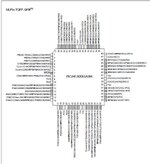
Which Pins do i need for UART, SPI or I2C communication?
 

Attachments

  • pic24fj.JPG
    pic24fj.JPG
    83.2 KB · Views: 68
If the device doesn't have an internal read function in firmware, I'm pretty sure you have to use one of the PGEC and PGED (C - clock, D-data) pin pairs and put the device in programming mode first. I don't think you can read it directly by any normal serial link like the ones you mentioned. I think you need a dedicated programming device such as a Pickit or similar.

Brian.
 
I do not steal anything dude, it's a Prototype Board from a Friend of maine, and i would like to bypass the security bit, for education purpose only and with his agreement!!
Um, why don't you ask your "friend" for his code, instead of going through all this nonsense.
I, for one, don't believe you.
 
@IntronDSOs - the short answer to your question about using something else to read/write the firmware is "no" (As (@betwixt has said above). Also I've answered the question about the pins in my previous reply, but to repeat: I2C have dedicated pins so look for SDA1 and SCL1 (for the first I2C module) and so on; the UART and SPIP modules use PPS so you will need to ask your friend which ones he used (they will be labelled RPnn or possibly RPInn in the pinout diagram you have shown).
I suspect by your questions that you are several layers of understanding away from doing whatever you actually want to do.
For a start, are the devices you have just the chips or are they mounted on a board of some sort? If a basic chip then how are you going to mount them so you can access the pins? If it is a board, then it may or may not already have a programming header on it - and if it is a 'development' board such as the MicroChip 'Explorer' boards then it may already have a programmer on it. Also, if it is a custom board then it may be that the pins youy need to access to read the firmware are already used for other purposes that will interfere with your ability to read and write the firmware.
Do you know the protocols that the UART, SPI and I2C communications use? Remember that these are the low level standards that are used for general purpose communication and what is built above those is probably developed by your friend.
If you don't have a programmer, then perhaps you should ask your friend for his as he will have used something to program the chips in the first place.
Finally, if the chip has not disabled it, the pins are accessible and not used for something else, then you might be able to use the JTAG interface to read/write the code on the unprotected chip. For that you will still need a JTAG programmer.
Susan
 

LaTeX Commands Quick-Menu:

Similar threads

Part and Inventory Search

Welcome to EDABoard.com

Sponsor

Back
Top