Continue to Site

Welcome to EDAboard.com

Welcome to our site! EDAboard.com is an international Electronics Discussion Forum focused on EDA software, circuits, schematics, books, theory, papers, asic, pld, 8051, DSP, Network, RF, Analog Design, PCB, Service Manuals... and a whole lot more! To participate you need to register. Registration is free. Click here to register now.

Buzzer intermittently fails to stop and emits continuous low volume buzzing

itelec

Junior Member level 1
Joined
Jul 27, 2024
Messages
15
Helped
0
Reputation
0
Reaction score
0
Trophy points
1
Activity points
114
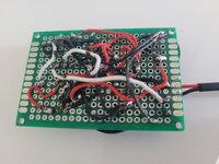
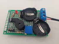
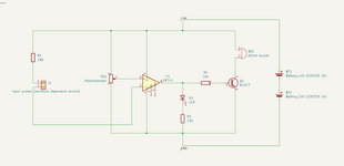
I created this hobby project to make a buzzing sound and turn on an LED when a moisture-dependent resistor detects moisture. Initially, I built the circuit on a breadboard, and everything worked fine. Then, I manually soldered everything onto a custom PCB with batteries in separate plastic compartments, which also worked perfectly. To save space, I moved the batteries onto the PCB, but now the buzzer intermittently emits a continuous low-volume buzzing. I suspect this issue is due to interference from the batteries.

I know the best solution might be to start over, separating the batteries from the rest of the circuit and shielding everything. However, I'm unsure how to best separate the components to avoid this behavior. Do you have any suggestions on solving this issue with the current PCB or designing a PCB with both batteries and components? Any optimization tips would be much appreciated, as I am not very experienced with analog circuits.
 

Attachments

  • pcb-back.jpg
    pcb-back.jpg
    3.2 MB · Views: 91
  • pcn-front.jpg
    pcn-front.jpg
    2.5 MB · Views: 68
  • circuit.png
    circuit.png
    41.3 KB · Views: 79
Those of us with some years experience will be picking ourselves up from the floor.

1. Batteries do not cause interference
2. 741 op-amps will not work properly with only 5 (or 6) volts supply
3. even if the 741 would work, its output can't go anywhere near ground or supply voltage
4. even if the 741 would work, it will be unstable without decoupling capacitors
5. leaving pin 2 floating if the probe is disconnected is asking for problems.
6. the construction is more artistic than functional!

The minimum you should do is:
1. use a comparator instead of an op-amp and one that will work at low supply voltage (LM139 etc.)
2. add decoupling capacitors
3. add a high value resistor from the probe input to ground to stop it floating.

Brian.
 

    itelec

    Points: 2
    Helpful Answer Positive Rating
Hi Brian

Thank you so much for your answers. They are very useful since I do not have any experience at all creating this kind of circuit.

1. Oh, I see. That explains why the batteries stopped working quite fast. What about using an LM358N? It operates down to 3V. It's not as low as the 2V comparator, but I think it would be easier for me to replace the current op-amp with this component.
2. I'm not quite sure where to add these capacitors. Any suggestions are highly appreciated.
3. What size resistor would you recommend?
 
1. LM358 would be much better. The difference between a comparator and op-amp is how the output changes. Op-amps are optimized to allow the output pin to swing between high and low in a linear way, comparators are designed to change state abruptly as the inputs swap polarity.

2. The problem with instability, especially using op-amps, is that tiny changes in the supply voltage can appear in the output signal. What tends to happen is the buzzer starts to sound and draws current as it does so, this drops the supply slightly an that in turn changes the op-amp output. You get a feedback loop. What you should do is add one capacitor of about 10uF directly across the ground and supply pins of the op-amp. Ideally you would add a second capacitor across the first one but use a smaller and ceramic type between 10nF and 100nF. This filter out the supply noise before it enters the amp and help to break that feedback loop.

3. I suggest a relatively high value, maybe 470K. The input pin on the IC draws very little current and left disconnected will be prone to static and interference pick up. Adding the resistor will hold it in a fixed state without having too much effect on the main current path through the sensor.

There is a further modification you could try, adding hysteresis to avoid a borderline condition where it intermittently operates. Get it working for now and then we can explain how to do it.

Brian.
 

    itelec

    Points: 2
    Helpful Answer Positive Rating
Thank you for explaining why a comparator is better than an op-amp for this circuit. It makes sense since it needs to switch between high and low instantly to activate/deactivate the buzzer. I don’t have any comparators yet, but I just ordered some. The LM393 operates at low voltage, so I'll try that one. I'll also consider your other suggestions.

1. Do you think the current battery position could be an issue
2. I know my prototype's design isn't optimal. Should I keep the batteries away from other components on the board?
3. Is it a bad idea to have wirering underneath the batteries?
 
1. Battery position makes no real difference in this application. The only time it becomes important is when the distance is great and a voltage drop could occur along the wiring length because of its resistance. The current drawn by your unit should be very small so the wiring length will not be an issue.

2. As above, the battery position has almost no effect on operation. Batteries themselves do not cause any interference so they can be placed wherever convenient.

3. Makes absolutely no difference. Planning the wiring is more important but only so there is less chance of wrong assembly. When you are more experienced you will find that designing a printed circuit board makes wiring much easier and probably smaller.

Brian.
 

    itelec

    Points: 2
    Helpful Answer Positive Rating
IMHO your batteries are undersized for your circuit or
your circuit is overloading the batteries.
Assuming these are Lithium 1" 1Ah batteries, the nominal efficient load is about 2.7kohm.
There is too much current drawn by the (TBD) buzzer.
The LED is redundant.

You have not reported the lowest voltage in your tests or the buzzer resistance or model #.

To prove my point I can simulate with a 741 and make it work using larger resistance but the same unnecessary LED. Note the battery ESR and voltage drop are my estimates.

For these batteries, your no alarm current should be 100 uA and your alarm current 1 to 2 mA max. using only a piezo alarm and low current comparator.

Your bridge R of 180 increases wasted current. So I changed it towards 50k.
 
Last edited:

    itelec

    Points: 2
    Helpful Answer Positive Rating
Thanks for the explanation, D.A. (Tony) Stewart. I'll proceed with the comparator.

Brian: I am waiting for the components for the second prototype. I'll try to make a schematic and get back. I am glad to hear the positioning of the batteries shouldn't be an issue regarding interference when the wirering isn't longer than it is.
 
Just to follow up on this thread. I got the circuit working as expected by replacing the op amp with a comparator and adding the capacitors as described. Thank you very much for the assistance.
 
Hi,
by replacing the op amp with a comparator

I don´t know how often I told in this forum:
* If you want a comparator function (output is either HIGH or LOW) --> use a comparator
* if you want to amplify a signal (not saturating) --> use an OPAMP

and I also wrote:
* in my eyes an electronics circuit without capacitors is no reliably working circuit (treat it with a grain of salt)

Klaus
 
Hi,


I don´t know how often I told in this forum:
* If you want a comparator function (output is either HIGH or LOW) --> use a comparator
* if you want to amplify a signal (not saturating) --> use an OPAMP

and I also wrote:
* in my eyes an electronics circuit without capacitors is no reliably working circuit (treat it with a grain of salt)

Klaus
I can imagine, but I must say. Those comments are very helpful when you aren't that experienced :)
 
Hi,

there are two big problems:
* there is so much garbage in the internet.
* unexperienced designers tend to look for "simple solutions". Four components look simple --> so let´s use it.

I can only recommend to use reliable sources of informations. The informations are more complex, but they need to, to descripe the function, giving math, giving other backgorund informations. They tell how to build a reliably working circuit, tell you what to look for. The many pages, the formulas, the terminology .. may be a bit distracting. But the more you are experienced the more you see how important these informations are. For sure - there may be informations not needed for your current appliaction, then ignore them. But you might need to know these infromations for a future project.

Reliable sources are:
* semiconductor manufacturers (datasheets, application notes, design notes, design support, online design tools, online calculators, online simulation..)
* universities
* reputable designers
* schools and their tutorials
...

****
A comment about comparator vs OPAMP:
There are opamps, where the datasheet show example circuits how to use it as comparator. Then there is nothing to say against it.
But mind that only some OPAMPS are able to work as comparators. But other OPAMPs may refuse to work (depending on input signals), some may give the reversed output, some may oscillate, some may even get killed.

Power supply / capacitors:
Many datasheets tell that the IC expects a low impedance (stabilized by capcitors) power supply. I prefer this, even if it is just given as a side note, because it is urgent for reliable operation.
Some datasheets don´t mention this. They expect this information as common sense in electronics design.

In any case:
* I recommend to put a fast (ceramics) capacitor very close to every single power supply pin of every IC.
(In my designs it is not uncommon to have 50+ pieces of 100nF ceramics just for power supply)
* "Very close" in the meaning of very low loop impedance. This means the other leg of the capacitor has also very short connection to the solid GND plane.
* And "solid GND plane" really means "solid", it does not mean "copper pour", where the GND is cut into many pieces.

Klaus
I appreciate the tips, Klaus.

I do my best to consult datasheets and online tutorials, but some circuits are challenging to grasp without experience. I'm not just seeking quick answers. I want to learn and understand the concepts. It can be difficult to find solutions when you're unsure what to search for.
 
Little piezo beepers can work to very low voltages and take little current so any switch leakage or "sneak path" might light it up adequately. A 3-15V part does not guarantee that it will quit working below 2.99V, only the converse.

Simplest fix might be to put DMM in current mode across the still-squealing beepers, see how much current is being pushed down it, and add a shunt resistor across to steal it (enough to make it shut up, like under 0.5V).
 

LaTeX Commands Quick-Menu:

Part and Inventory Search

Welcome to EDABoard.com

Sponsor

Back
Top