boylesg
Advanced Member level 4

- Joined
- Jul 15, 2012
- Messages
- 1,023
- Helped
- 5
- Reputation
- 10
- Reaction score
- 6
- Trophy points
- 1,318
- Location
- Epping, Victoria, Australia
- Activity points
- 11,697
I am currently using TC4422 gate driver chips to drive the gate of my mosfet in my flyback transformer driver.
With the musical solid state tesla coils it seems as though people, in some cases, use some sort of AC flyback transformer or ignition coil to supply HV to the tesla primary.
And with musical tesla coils it appears that the power interruption to the tesla coil, for modulation purposes, takes plase at the gate of the mosfet powering the flyback or ignition coil. I have seen examples where folks are using gate driver chips with an enable/disable pin and their audio modulation circuitry interfaces with this pin.
My TC4422 does not have an enable/disable pin and it would be good to figure out a way to use them rather than having to buy new gate driver chips.
I was thinking along the lines of either:
1) Passing the output of my 555 through a PNP transistor and then modulating the signal via the base of this transistor.
2) Passing the output of the TC4422 through a PNP transistor........
Are there any cons to doing the modulation this way?
- - - Updated - - -
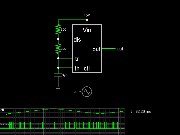
As I understand it currently, the control pin of a 555 varies the duty cycle of the pulse like this:

So I presume there is a low limit to how much audio power you can transfer to an arc via this method since varying the duty cycle varies energy in the carrier signal.
I.E. You get more powerful arcs with a duty cycle of 90% than you would with a duty cycle of 10%
And I presume there are limits on to what degree control pin can vary the duty cycle.
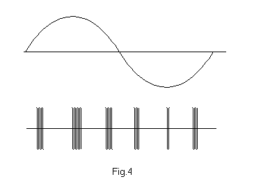
As I currently understand it musical tesla coils do this sort of modulation:

Where the duty cycle of the carrier signal is always the same but the time gap between bursts of pulses and the length of the bursts varies according to the sound signal. I presume you can transfer a great deal more audio power this way by lengthing the bursts of pulses.
Am I correct so far?
With the musical solid state tesla coils it seems as though people, in some cases, use some sort of AC flyback transformer or ignition coil to supply HV to the tesla primary.
And with musical tesla coils it appears that the power interruption to the tesla coil, for modulation purposes, takes plase at the gate of the mosfet powering the flyback or ignition coil. I have seen examples where folks are using gate driver chips with an enable/disable pin and their audio modulation circuitry interfaces with this pin.
My TC4422 does not have an enable/disable pin and it would be good to figure out a way to use them rather than having to buy new gate driver chips.
I was thinking along the lines of either:
1) Passing the output of my 555 through a PNP transistor and then modulating the signal via the base of this transistor.
2) Passing the output of the TC4422 through a PNP transistor........
Are there any cons to doing the modulation this way?
- - - Updated - - -
As I understand it currently, the control pin of a 555 varies the duty cycle of the pulse like this:

So I presume there is a low limit to how much audio power you can transfer to an arc via this method since varying the duty cycle varies energy in the carrier signal.
I.E. You get more powerful arcs with a duty cycle of 90% than you would with a duty cycle of 10%
And I presume there are limits on to what degree control pin can vary the duty cycle.
As I currently understand it musical tesla coils do this sort of modulation:

Where the duty cycle of the carrier signal is always the same but the time gap between bursts of pulses and the length of the bursts varies according to the sound signal. I presume you can transfer a great deal more audio power this way by lengthing the bursts of pulses.
Am I correct so far?