Continue to Site

Welcome to EDAboard.com

Welcome to our site! EDAboard.com is an international Electronics Discussion Forum focused on EDA software, circuits, schematics, books, theory, papers, asic, pld, 8051, DSP, Network, RF, Analog Design, PCB, Service Manuals... and a whole lot more! To participate you need to register. Registration is free. Click here to register now.

Building a replacement board help!

Status
Not open for further replies.

TakingYouOHMs

Newbie level 3
Newbie level 3
Joined
Aug 27, 2014
Messages
3
Helped
0
Reputation
0
Reaction score
0
Trophy points
1
Activity points
27
Good morning everyone!

I'm new to building boards and have been working on small projects but I'm currently hitting a bit of a wall. I began building a board for a friend who has a sound Super 8mm sound projector. We were replacing the old board on the machine that he bought off Ebay. When the board came it was in terrible condition:
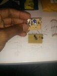
IMG_20140715_104831.jpg

The picture is also missing the power connector that powers the LED externally and potentiometer that fell off the moment I picked it up. I feel a bit overwhelmed with this board, no schematic with it or anything, kinda got shafted but I know it's not impossible to create another. Is there anyone that could possibly give a few pointers or some small assistance, it would be great appreciated.
 

I find it funny that in the background there is a black anti-static bag with an ESD sticker on it and the picture shows someone holding the board without an anti-static mat and no ground strap. The parts look to be at an older technology node so are likely somewhat less susceptible to ESD events under 2000V (but don't count on it).

You need to look at all the existing connections and draw a schematic of the circuit before anything else falls off. Then figure out what fell off and how it was connected and add that to the schematic. Once you have the schematic, I'm sure if you post it you'll get some feed back to whether or not it's drawn correctly and what might be still missing and/or connected incorrectly.

Regards
 

What is the board meant to do?
Frank

It was meant to power the LED for the projector. The previous owner replaced the old incandescent bulbs.

I find it funny that in the background there is a black anti-static bag with an ESD sticker on it and the picture shows someone holding the board without an anti-static mat and no ground strap. The parts look to be at an older technology node so are likely somewhat less susceptible to ESD events under 2000V (but don't count on it).

You need to look at all the existing connections and draw a schematic of the circuit before anything else falls off. Then figure out what fell off and how it was connected and add that to the schematic. Once you have the schematic, I'm sure if you post it you'll get some feed back to whether or not it's drawn correctly and what might be still missing and/or connected incorrectly.

Regards

I had a wrist grounder on during the picture on my left arm :)

I am currently trying to draw it up, been a little rough but I'll post it asap. Thanks.
 

The last time I used my 8mm projector was about 25 years ago, then I transferred all my old home movies onto video tape than later into digital.
Why is your friend still trying to use the old projector?
Why not use an original incandescent light bulb? Is it obsolete?
 

The last time I used my 8mm projector was about 25 years ago, then I transferred all my old home movies onto video tape than later into digital.
Why is your friend still trying to use the old projector?
Why not use an original incandescent light bulb? Is it obsolete?

Using it for projection (he's a bit of a hipster artsy farsty type) but also I plan of creating a HD camera mount that will record the 8mm to digital to archive some of the old 8mm stuff his and my family have laying around for Christmas.

The old bulbs were just inconsistent and we wanted to make some mods to the projector, honestly it's more of a passion project.
 

So Google around to find out what projector bulb replacement LEDs are. Look up their typical characteristics. i.e. 4V @ 2.5 A or such like. Then Google again for circuits for 4V, 2.5A LED drivers.
Frank
 
Find out how many LEDs in series are used and Volt/Amp rating of LEDs.

This can be done using LM317 as an adjustable constant voltage or current source, but this current source has a higher power loss. Judging by lack of heatsink, it must get hot.

is it a 50W 12V LED or 100W, 50V LED (1" dia.)

In the end, best solution depends on V, I you need and supply & parts on hand.
 

Status
Not open for further replies.

Part and Inventory Search

Welcome to EDABoard.com

Sponsor

Back
Top