Continue to Site

Welcome to EDAboard.com

Welcome to our site! EDAboard.com is an international Electronics Discussion Forum focused on EDA software, circuits, schematics, books, theory, papers, asic, pld, 8051, DSP, Network, RF, Analog Design, PCB, Service Manuals... and a whole lot more! To participate you need to register. Registration is free. Click here to register now.

BTHR918N Displaying Consistently Low R Reading (weather station)

Status
Not open for further replies.

AtomicPlayboy

Newbie level 4
Newbie level 4
Joined
Jan 12, 2018
Messages
6
Helped
0
Reputation
0
Reaction score
0
Trophy points
1
Activity points
101
Hi,

I have an Oregon Scientific WMR928N weather station, which I've owned from new for many years. It has an indoor baro/temp/humidity sensor (BTHR918N) that works well enough aside from the relative humidity (RH) reading, which is significantly lower than my other hydrometers sat side by side with it. I understand from internet research that the humidity sensor component inside the unit deteriorates over time. This is bourn out by the fact that a replacement I installed, a HCZ-H8-B humidity sensor, increased the very inaccurate current 11% RH reading to 40%. However, it is still too low by about 7% but increases and decreases accurately with my other sensors. Inside the unit there is a preset (R12 10K) that appears to me to be for the purpose of calibrating the humidity sensor but at best it looks like it only attenuates an already low reading, i.e. at 0R resistance it is only ever at its maximum capable RH reading, which is still too low.

My question is, other than trying to find a RH sensor that is more sensitive to humidity (not likely I guess), is there a way of modifying the circuit to be able to adjust the sensitivity in order to provide a more accurate reading on the unit's LCD display? BTW, I am aware of PC weather station software being able to offset the readings but I am interested in fixing the LCD readout only.

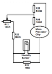
Attached image below is of the new sensor installed and immediately beside it the now faulty and out-of-spec original sensor. The second image is a section of the schematic for this sensor (BTHR318N) unit that I worked out from following the tracks from the microprocessor "blob" to the RH sensor and back to the microprocessor.

BTHR918N RH Sensor.jpg

BTHR918N RH Sensor Circuit.png

Also, here is the RH sensor datasheet for the HCZ-H8-B if it's of any use:
https://www.farnell.com/datasheets/1355478.pdf.

Any advice would be greatly appreciated.
 

Re: BTHR918N Displaying Consistently Low R Reading

That schematic doesn't help a lot; showing lines going into a bubble labelled "Micro" doesn't tell us much. Where is ground? Where is voltage? Where's the input? Did this ever work properly? I could speculate, but it would be better if you just drew a clearer schematic.

Looking briefly at the data sheet, the device has a +/- 3% error. It also has a 0.3%/deg. "temperature dependence". If your temperature deviates 10 degrees, that's another 3% error, which puts us close to your 7%.
 

Re: BTHR918N Displaying Consistently Low R Reading

Thanks for you reply. Believe me, I'd like to provide more on the schematic side but Oregon Scientific don't provide that data. It may be close to the outside limits of the specified accuracy but it's never been that awful in terms of accuracy, more like the +/- 2%. The sensor circuit pictured is only energised about every 38 seconds, so it's difficult to make any meaningful measurement (unless you can think of something?). The whole unit runs on 6V and the brief voltage I can see with a DVM is just over a volt for about half a second. If it's too little to go on, then I'll trash it as I don't have the know-how to investigate it much further.
 

Re: BTHR918N Displaying Consistently Low R Reading

I guess the simple answer is you could try adjusting a resistor to give you more gain, but that might affect the linearity.
 
Re: BTHR918N Displaying Consistently Low R Reading

Yes, I was thinking that myself and that it couldn't simply be a case of perhaps replacing R23 with a lower value resistor without perhaps affecting something fundamental. Anyway, I tried a 220K resistor in R23's spot and the % reading came up to ~65%, so that change "works" in terms of moving calibration center but obviously going to need to increase the resistor value to get it to around the current indoor RH here which is around 47%. But, like you say, is my linearity messed up? I guess what I can do is use a damp wrap around my working hydrometers for set times to see if I can work out some kind of RH scale I can then check against my modification. What do you think? Thanks for your thoughts by the way.
 

Re: BTHR918N Displaying Consistently Low R Reading

Adding a parallel resistor is unlikely to correct for a RH sensor with different impedance. It shifts the RH value but also further reduces the gain. Instead changing R18 and/or R20 might do.


But unfortunately, it's impossible to decide in advance without knowing about the connected microcontroller circuit function.
 
Re: BTHR918N Displaying Consistently Low R Reading

Hi FvM,

I reduced the resistance of both R18 an R20 but not both at the same time. I reduced R18 to just under 5K and R20 to about 30K but neither change appeared to make any difference. I'll try reducing both at the same time to see if that makes any difference.
 

Re: BTHR918N Displaying Consistently Low R Reading

While it's pretty clear that changing R23 can't scale the circuit for different sensor impedances, the effect of R18 and R20 can't be determined without understanding the circuit function. My assumption was apparently wrong, worst case there's no option to adjust the sensor sensitivity without modifying the software.
 
Re: BTHR918N Displaying Consistently Low R Reading

To calibrate your humidity scale, there is a method of moistening a capful of salt with water, then placing it in an airtight container with your meter. Allow several hours for vapor pressure to reach equilibrium. Then the meter should read 75% humidity. Prevent salt from contacting the meter.

Example article:

https://www.wikihow.com/Test-a-Hygrometer
 
FvM, I think it turns out your assumption was correct. I didn't recall when I replied to your message that the RH % dropped like a stone to 2% when I changed R20 to about 30K. So, I tried increasing the resistance instead and pleasingly the RH value increase. It stays at 2-3% until the resistance reaches roughly 45-50K then starts to rise. I installed a 500K in R20's space and watched as the RH value increased as resistance increased. At around 500K the humidity peaked at 47%, which was at the time just where I needed it. I then replaced the 500K pot with a 1M resistor and the reading maxed out at 50%. Higher resistances make no difference to the max 50%.

I wondered what a different humidity sensor component might do so I took a broken desk weather station and took out the sensor, which appears to have more surface area given over to the sensitive polymer material. This sensor gives a reading roughly 10% higher than the HCZ-H8-B, so I was able to lower the resistance of the pot. On the HCZ-H8-B the port resistance measures 190K (47%) to achieve what I believed to have been the correct room RH at that time, according to my other sensors. I then measured the resistance of the pot with the second more sensitive sensor and that showed 120K, so just over twice the original resistance. I haven't changed R18 (10K) as it's a SMD and although I bridged it to achieve 5K to test a lower resistance at in its position I would be concerned I'd end up damaging the resistor or tracks with a regular soldering iron. I do have a hot air iron as well, if necessary for any further tests. By the way, all resistors are 1% tolerance.

So, I guess the next step is deciding if changing R20 is a sufficient mod on its own or if I need to some more tests. I think I should mention that R20, R22 and R23 are all through-hole type resistors soldered to solder pads rather than through holes, almost as if they designer expected them to need to be changed. I don't know, perhaps not but you can just see two of them in my attached photo in my first message.

Thanks for you continued assistance on this all. :)

Thank you very much BradtheRed for your message. I hope that will come in very useful once I have the circuit mod-ed to provide an accurate reading.
 

Status
Not open for further replies.

Part and Inventory Search

Welcome to EDABoard.com

Sponsor

Back
Top