Continue to Site

Welcome to EDAboard.com

Welcome to our site! EDAboard.com is an international Electronics Discussion Forum focused on EDA software, circuits, schematics, books, theory, papers, asic, pld, 8051, DSP, Network, RF, Analog Design, PCB, Service Manuals... and a whole lot more! To participate you need to register. Registration is free. Click here to register now.

Breadboard Power Supply: How to use hot & neutral wires from a wall adapter?

Status
Not open for further replies.

KalELonRedKryptonite

Newbie level 4
Newbie level 4
Joined
Feb 21, 2014
Messages
7
Helped
0
Reputation
0
Reaction score
0
Trophy points
1
Activity points
65
Hello,

I'm a new student to electronics and I have a question regarding supplying power to a breadboard with a wall adapter.

I took an extra AC to DC wall adapter from an old Blackberry and cut the USB end off of it so I could use the wires. I know the smooth/round wire is the hot wire and the ribbed wire is the neutral wire (output is 5V and 700mA).

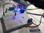
I am confused on how to use it to supply power to my breadboard as the way I tried did not light up my LED. I am testing it with a 5mm blue LED, a resistor connected to the negative rail, and a jumper wire to connect the LED to the power rail.

I plugged screw terminal blocks into the positive and negative rails on the breadboard and tried to connect the hot wire to the positive and the neutral wire to the negative but it didn't work. Nothing happened.

So, my question is how do I used this adapter to power my breadboard?

I'm not sure how to make it work. (I do have a Raspberry Pi that I am able to use the GPIO pins to connect to my breadboard to power the LED, but no luck so far with the wall adapter.)

Thank you, I appreciate any help and advice.
 

Hmm, it was only a 470 Ohm 1\4W 5% resistor. What about the wires, did I use them correctly or not with the breadboard?
 

LED the wrong way around?
Also note that the terms 'hot' and 'neutral' apply to the AC wall socket connections, the low voltage wires that went to the phone are positive and negative DC.

Brian.
 
I know the smooth/round wire is the hot wire and the ribbed wire is the neutral wire (output is 5V and 700mA).

I'm not clear on what you mean, did the cable have a just one central conductor and the braid around it?
Can you attach an image?
 

You should have seen it before.

Coaxial design of low voltage power supply cables is pretty standard, also for notebock power adapters. You get a neat round cable with smaller diameter than paired wires for same cross section.
 

Yes I have seen a coaxial cable used but the connection is not working for him so maybe there is something we are missing from the description and an image will help.
I also want to make sure that there is just a single core in the cable.
 

Obviously the polarity of the DC is backwards. Reverse the wires from the adapter and it will work but the blue LED needs about 3.3V and the 470 ohm resistor reduces the current to only (5V - 3.3V)/470 ohms= 3.6mA so it will be dim.
 
Thank you Audioguru!! That fixed it. So that means the ribbed wire is the positive? Interesting, I thought I read the opposite.

I put a smaller resistor on, 180 Ohms. I'm still trying to figure out the relationship between voltage, amps, and resistance; so if the power supply puts out 700mA, does that mean all 700mA's goes through the LED if the resistor was not there? And if so, then why does resistance usually only mention volts, what about the amps being resisted?

breadboard_experiment_LED.jpg
 

So the conclusion is, you have spend one day or so guessing about the voltage polarity of your wall adapter where a measurement with a multimeter would clarify this immediately.
 

I don't own or have access to a multimeter yet, have to wait until my next paycheck to pick one up. But yes, it is a great priority for me next.
 

I bought a digital multimeter for my son for only $10.00 and it works fine.

Leds the size of yours are spec'd with a current of 20mA. Over 30mA destroys them.
An LED limits the voltage across it and different colors have different voltages (look in Google). The resistor in series limits the current calculated with Ohm's Law (look in Google) and simple arithmatic:
You have a 5V supply.
Your blue LED is about 3.3V so the resistor has the difference of 5V - 3.3V= 1.7V.
Ohm's Law says the current is the Voltage across the resistor divided by the number of ohms= 1.7V/180 ohms= 8.4mA.
For 20mA then Ohm's Law says the resistor value is the Voltage divided by the Current= 1.7V/20mA= 85 ohms which is not a standard value so use 82 ohms which is close.
 

Attachments

  • LEDs.png
    LEDs.png
    14.6 KB · Views: 155
Yes, I have my eye on a $10 digital multimeter as well. (**broken link removed** - do you happen to know if this one is good for a cheap one or crap and don't bother?)

Looking through my packs of resistors, I have 47 & 100 Ohm's values that are the closest to 85. I have a few different types of diodes though. I think 1N4004 takes off .7 volts (?), which would drop it to 1 v / 47 ohms = 21.28 current, I believe?

100 won't work, it would drop to 10 current, but would that simply mean it would be half as bright (20/2=10)? I'll test it, have a pack of 50 so destroying some won't matter.
 

I bought my son's $10.00 DVM from a local store, not from Chinese e-bay. If anything goes wrong with it for 1 year then they will replace it IMMEDIATELY.

Do not add a diode in series to reduce 5V to 4.3V unless you measured the forward voltage of your LED because they are all different. It might be 3.0V, your 5V might actually be 5.2V, your diode might actually be 0.6V and your 47 ohm resistor might be 45 ohms. The current will be (5.2V - 3.0V - 0.6V)/45 ohms= 35.6mA and the LED will soon burn out.
What if your LED is actually 3.6V, the 5V is actually 4.8V, the diode is actually 0.8V and the resistor is actually 49 ohms? Only 8.2mA which will look dimmed.
 
I have the same DVM and it works fine.

lumens[measure for light, brightness, if you like] is somewhat linear over current, but your eye is non-linear. So what is half the lumens, may - to your eye - may seem only somewhat less bright. And it depends on the ambient light.

Is there any particular use of the LED that you have in mind? If it is an indicator [ie power is on], then 5mA is fine - you actually don't want it annoyingly bright.

If you want it BRIGHT, then try putting a 560 ohm resistor in parallel with the 100ohm - that would give 85ohms. although audioguru gives sound advice on measuring first.
 
As nobody answered... 700mA is the maximum current the adapter is rated to produce. It isn't a measure of how much it actually IS producing. The current you draw depends on your circuit and as long as it doesn't exceed 700mA the adapter will be happy. If you did try to draw more than 700mA the result is difficult to predict without prior knowlwdge of the circuit inside the adapter itself, some will shut down, some will overheat and burn out.

Brian.
 
Thanks Betwixt, I didn't realize all the current doesn't flow on it's own.


If you want it BRIGHT, then try putting a 560 ohm resistor in parallel with the 100ohm - that would give 85ohms.

Why does that make 85 Ohms and not 660?

As for the purpose of the LED, it's just the beginning experiments or 'labs' that most of the electronics books, tutorials, online courses start with. Right now I have a big bag of components from Tayda and a couple breadboards and wire supply. I do own a Raspberry Pi and I have an Arduino Uno R3 in the mail. Soon I will start bigger experiments than simply lighting LED's.

One thing that is confusing is the electrons flowing from negative to positive, but "conventional" says positive to negative... what? Ha.
 

Why does that make 85 Ohms and not 660?
560 ohms in series with 100 ohms makes 660 ohms. 560 ohms in parallel with 100 ohms makes 85 ohms.

One thing that is confusing is the electrons flowing from negative to positive, but "conventional" says positive to negative... what? Ha.
Because in the early days they didn't know about electrons so they got it (conventional flow) backwards.
 
Does that mean if one was a purist, they could ignore conventional thought and wire everything negative to positive and it would work the same?
 

Status
Not open for further replies.

Part and Inventory Search

Welcome to EDABoard.com

Sponsor

Back
Top