Vermes
Advanced Member level 4

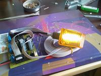
All mopeds have to be equipped with turn signals and brake lights, according to traffic regulations. Some older vehicles of this type don't have those, that is why brake light and turn signals of own production are very good idea.
The biggest problem is low productivity of olde mopeds' magnetos and as often their condition. Often these magnetos had only coil to power the ignition (low or high voltage) and the so-called 'light' coil to power the lights. There aren't any coils providing electricity to charge the battery in the vast majority of the old 'equipment'.
Turn signals were made with use of LEDs. The system described because of its very low power consumption compared to light bulbs, can be used in any older mopeds.
Assumptions were to build the system that at low power consumption allows to clearly indicate the start of braking or steering, the pure 'coil', even at idle.
For simple magnetos, a serious problem is the difference of output voltages at idle, and those, which engine develops while driving, especially when coils are unloaded. To eliminate this, a simple lossy regulator was used.
Schema:
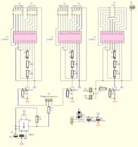
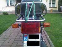
As it is shown, diodes aren't powered directly by the resistor, but a system of voltmeter 0-5V LM3914 is used. 3-series LED current setting resistor were used, in order to be able to accurately choose it. Two LMs power right and left sides of the turn signals (each 5 white diodes of 5mm, very bright), third one powers 10 'STOP' diodes in rear light.
NE555 was used in application of unstable generator of the fulfillment of 50% and frequency of 3 Hz to generate blinking of the turn lights.
Due to the nature of the voltage regulator and the specificity of its work (lossy, shorting the coil outputs in case of excessive voltage), the power supply is separated by two diodes and has a fairly large battery of capacitors.
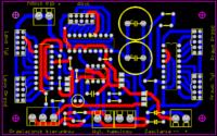
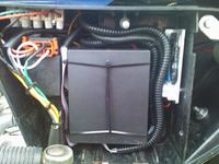
The board is two sided, paths quite wide and tinned.
After assembling all the two parts, all elements were covered with five layers of rosin – it's a good and checked protection from moisture.
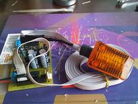
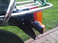
The housings of turn lights were bought on auction portal. Diodes have emery fumed lenses and are placed in suitable, tiny PCBs.
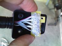
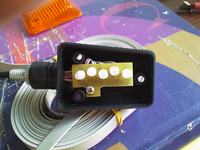
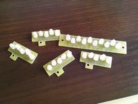
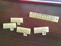
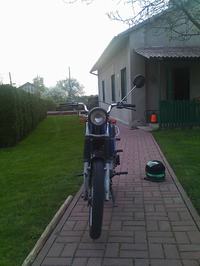
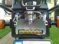
It can be mounted like that:
Link to original thread – Światło STOP i kierunkowskazy dla każdego motoroweru