praveen450
Member level 5

Hi,
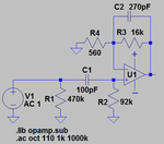
I'm implementing a BPF using Opamp and the microcap circuit file is attached to this post.
My question is
1) When I change vcc from 8 to 0V, when using dual power supply (12V) the filter is having gain. And when I'm using vcc open, I'm not seeing gain
2) When I remove vcc when using dual power supply the filter is having no gain.
3)If I have single power supply and biasing vcc at 6V gives me gain.
My question is when using dual power supply,
I should be able to get gain at no bias i.e when vcc is not connected in the circuit. Then why my active filter is not giving me a gain?
Help me with that..


