Hi,
I just wanted to simulate and see the advantage of "Bottom Plate Sampling".
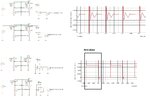
So, I have put the circuit as shown in attachment and simulated. The waveform is shown adjacent to the circuit. It depicts the difference in potential across two sampling capacitors(Eg: V(C2) - V(C3)).
The first part of the circuit has a ideal switch which doesn't offer any parasitic capacitance. When I simulate that 1st circuit, the difference in potential across the sampling capacitor is almost constant during Sampling and Hold phase.
But, in the second circuit I have added a parasitic capacitor of 10fF at the top node of ideal switch. The switch setup is same as that of previous one. Now, I could see a potential difference between both sampling and Hold phase. I believe it is because of charge injection.
Switching frequency : 100MHz


Anybody have any comment on this observation.
Thanks,
Jebas.


