Continue to Site

Welcome to EDAboard.com

Welcome to our site! EDAboard.com is an international Electronics Discussion Forum focused on EDA software, circuits, schematics, books, theory, papers, asic, pld, 8051, DSP, Network, RF, Analog Design, PCB, Service Manuals... and a whole lot more! To participate you need to register. Registration is free. Click here to register now.

Bootloader for PIC18F4550

Status
Not open for further replies.

TheFallenAngel

Newbie level 3
Newbie level 3
Joined
Sep 12, 2009
Messages
4
Helped
0
Reputation
0
Reaction score
0
Trophy points
1,281
Location
Malaysia
Activity points
1,337
Hello,can I write the control command in C if the boot loader in pic18f4550 is in assembly language?thank you.
 

In the end, everything you place on the PIC is translated into assembly code...

So, you can write your program code in whatever language you want. But you have to take care that the interrupt vectors and program vectors are defined correctly and match between the bootloader code and the program code.

Which bootloader are you using? Some bootloaders are located at the beginning of the flash memory, some are located at the end of the flash memory...
 

thank 4 ur reply,the bootloader is located at the beginning of the flash memory...
I already program the bootloader into the PIC....but when I plug in into the PC through USB, the PC cant detect anything,may I know how to solve this problem?
 

I am facing the same problems. May I know the solutions for this problem ?
 
  • Like
Reactions: yjbin

    yjbin

    Points: 2
    Helpful Answer Positive Rating
@ thefallenangel and
@nsw1216

there are a few things that you need to do for your PC to recognize the PIC, while connecting the PIC to USB, you need to keep the bootloader button pressed.(Normally at RC6 to ground with a Microchip PIC Demo bootloader)
On first use, the PC will ask for the driver of the USB device and you need to have the drivers ready.
I posted a tutorial regarding PIC and USB on my blog, since posting outside links in not encouraged here, you might give abidrehan.wordpress.com a try.
With the hope that I am not breaking any rules, just trying to help.
 
abidr,

Which hex file do you used for the bootloader ?
picdemfsusb.hex?
USB Device - HID - HID Bootloader - C18 - PIC18F4550.hex?
Based on my circuit, the push button switch is at RB4 not RC6 and i am using the USB Device - HID - HID Bootloader - C18 - PIC18F4550.hex for my bootloader.

Thanks for your reply.
 

well I have had experience with the PICDEM, only difference is I downloaded the sources and compiled it myself.
Personally i prefer PICDEM, as it takes less space compared to HID, the offset in later case is at x1000 while in prior it is at x0800
Ok you are using HID bootloader, you should try shorting RC6 to ground while connecting to USB, if windows ask for driver then you are good to go.
 

abidr,

Ok. May i know what is the difference between both type of bootloader ?
Do you have the download sources for the PICDEM ?
PICDEM = picdemfsusb.hex ?
Any reference of the circuits you used for your PIC ?
Why we need to ground the RC6 ?
But with the HID bootloader my PC cant detect my device ? WHy ?
About the tutorial you stated above, it is under which topic ?

Functionally not much difference between PICDEM and USBHID, except that PICDEM occupies less programming space than USBHID.
PICDEM yes this is PIC demo.
Circuits, Hex files are available on the tutorial page under the heading of PS3.
Try reading from the MCU, (assuming that you are using PICKIT) if there is something except "FF" between 0000 to 1000 then you did program the bootloader successfully, otherwise there was error in the write operation. My guess is that either the PIC was not programmed successfully, the capacitor at VUSB is not connected, or you have connected the USB in reverse. There was another issue with the bootloaders, once you program it in the mcu the bootloader button is at RB4, but after uploading the main program the bootloader button shifted to RC6.
Sources of bootloader are available at microchip website under USB framerwork.
 
abidr,

Thanks for the explanations.
Wanna ask that will the data lost if i use pcb connector without using the usb socket connecting the PIC unit to the PC ?

Regards,
nsw1216
 

Simple answer is no.

Unless you overwrite the bootloader, or erase the chips altogether you cant loose the data.
 

There was another issue with the bootloaders, once you program it in the mcu the bootloader button is at RB4, but after uploading the main program the bootloader button shifted to RC6.

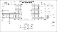
well, this could be one of the mistakes i am making, but then, how do i find which button is being used as the bootloader button from the source code? i am using the Serial Bootloader AN1310 v1.04 for pic18f4550

---------- Post added at 23:11 ---------- Previous post was at 21:51 ----------

i was going through the Microchip AN1310 documentation when i came across this schematic:

and now i am confused, i am thinking, that if i use the AN1310 bootloader, i will have to use the above schematic to go into bootloader mode, and if i use the MCHPUSB.hex bootloader, i can use this:

circuit to go into bootloader mode by pressing bootloader button and reset......
am i right? because i am using AN1310 bootloader with the second circuit with no success......
 

Why would you need to use a serial bootloader over a USB connection?
I have my serious doubt that the serial bootloader will work for second circuit. Though I never tried it myself.

You could easily find the USB bootloader sources at microchip website under USB infrastructure 2.2, and if you are interested in ready made hex files of USB bootloader, just go to any decent PS3 Jailbreak scene forum and you can find plenty of different bootloaders.
 

abidr,

Thanks for the guidance. My circuit is working finally.
 

Appreciate if you post the reasons, and what you changed that made your circuit to work.

It will definitely help others.
 

abidr,

Actually is not my circuit problem. It's working fine if my push button for bootloader remained at RB4. It's my PIC problem, i realized that my PIC doesn't programmed with bootloader properly after i try to read my PIC. AS you menetioned, the bootloader will be located between 0000 to 1000 and others are FFFF.Then i try to reprogram it again until i read the correct data from the PIC.
 

yes, thats what i figured...... so i changed the bootloader, since i was using the CUI [
schematic, i tried the bootloader provided on the CUI site, which has the bootloader switch on RB5, whereas the Microchip HID bootloader has the bootloader switch on RB4, and this was the problem that was not allowing my circuit to go into bootloader mode. now, atleast when i connect my pcb to the computer, it detects a new hardware, which means i have got it right, but now, when windows asks for a driver, i select the .INF file, but it says no driver file detected.
so now i am gonna try the Microchip HID bootloader, see if i can get it to work........
but then, i have been wondering if i will have to make

this circuit to use the serial AN1310 bootloader.... and if so, how do i get that +3.3V supply? can i use a voltage regulator (12V-to-3.3V) directly on the RS232 +12V supply? ( RS232 is completely new to me)
 

abidr,

Which hex file do you used for the bootloader ?
picdemfsusb.hex?
USB Device - HID - HID Bootloader - C18 - PIC18F4550.hex?
Based on my circuit, the push button switch is at RB4 not RC6 and i am using the USB Device - HID - HID Bootloader - C18 - PIC18F4550.hex for my bootloader.

Thanks for your reply.
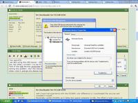
hey nsw1216.
i am also using the USB Device - HID - HID Bootloader - C18 - PIC18F4550.hex for my bootloader. i have got the circuit right too, but when i connect it to my PC, i get a message saying:
"one of the USB devices attatched to this computer has malfunctioned, and Windows does not recognize it. For assistance in solving this problem, click this message"
when i click it and go into device manager, it lists my device as "Unknown Device".....

Microchip's HIDBootLoader.exe program also does not detect it.
what am i missing?

---------- Post added at 20:12 ---------- Previous post was at 19:44 ----------

aaaaahhhhh...... i messed up bad...... i had connected the D+ and D- ports on the USB wrong..... got it now..... HURRAY!! :)

---------- Post added at 20:30 ---------- Previous post was at 20:12 ----------

but i am still wondering......
but then, i have been wondering if i will have to make
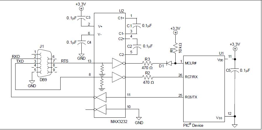
9_1299208135.jpg

this circuit to use the serial AN1310 bootloader.... and if so, how do i get that +3.3V supply? can i use a voltage regulator (12V-to-3.3V) directly on the RS232 +12V supply? ( RS232 is completely new to me)
any ideas??
 

prash42135 ,

First thing check your bootloader is programmed properly or not as stated by abidr above.
Second, check for sequence for push button to load into bootloader mode.

What are you asking about the circuit ?

regards,
nsw1216
 

Status
Not open for further replies.

Similar threads

Part and Inventory Search

Welcome to EDABoard.com

Sponsor

Back
Top