Continue to Site

Welcome to EDAboard.com

Welcome to our site! EDAboard.com is an international Electronics Discussion Forum focused on EDA software, circuits, schematics, books, theory, papers, asic, pld, 8051, DSP, Network, RF, Analog Design, PCB, Service Manuals... and a whole lot more! To participate you need to register. Registration is free. Click here to register now.

Biquad filter

houly75

Newbie level 4
Newbie level 4
Joined
Dec 23, 2009
Messages
6
Helped
0
Reputation
0
Reaction score
0
Trophy points
1,281
Location
Paris
Visit site
Activity points
1,358
Hello,
I'm looking for a method that permits to "convert" Laplace transfer function of a biquad filter to a block diagram (in order to transform into a schematic). I read a few books about this subject (filters) but all of them give a partial answer and not a description of the method used. For example this is an extract of "ANALOG FILTER 2sd edition" (Kendall Su)

1735915874595.png

1735915622900.png

Do you know a reference book which permits to help me to better understand the method ?
 

Attachments

  • 1735915523194.png
    1735915523194.png
    115.7 KB · Views: 19
Also Analog and Digital Filters: Design and Realization : Lam, Harry Y. F, Paragraph 10-2-2 Multiple Amplifier Biquad

The excerpt in post#1 is crystal clear, I think. The only open point is how to implement adders, substractors and integrators with OPs, apparently taken as granted.
 
Last edited:
Hello,
I'm looking for a method that permits to "convert" Laplace transfer function of a biquad filter to a block diagram (in order to transform into a schematic). I read a few books about this subject (filters) but all of them give a partial answer and not a description of the method used. For example this is an extract of "ANALOG FILTER 2sd edition" (Kendall Su)

Do you know a reference book which permits to help me to better understand the method ?
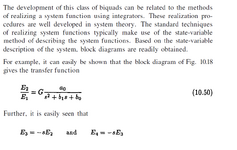
The classical established procedure is as follows:

* A transfer function to be realized is given
* The form of the transfer function reveals the general cahracteristic of the filter
* From this, a circuit topolgy is selected for realzation
* From the circuit, a block diagram can be derived.

Explanation: A given transfer functions can be realized with different circuit topologies with corresponding block diagrams.
Therefore, there is not only one single method to visualize the function with a block diagram
By the way - only well experienced enginners are able to create a block diagram directly from the transfer function - without having before a circuit diagram.
 
Last edited:
Thanks all for your replies,
Well, they mention state variable method (that I don't know well)
as mentioned in the textbook :
"Based on the state-variable description of the system, block diagrams are readily obtained."
It seems that block diagram can be deduced by inspection of the expression but the form of this expression is not presented in the book (it may be obvious but not for me).
In fact, I'm looking for a book that could help me to introduce State variable method.
 
'Active-Filter Cookbook' by Don Lancaster. Howard Sams publisher. I have 1975 edition.

'Audio IC Op-Amp Applications' by Walter G Jung. Howard Sams publisher. I have 1978 edition.

Both books give several pages to state-variable filters, and mention bi-quad also. The example circuits have 3 op amps connected each providing a different filter output (usually low-pass, high-pass, bandpass).
 
Thanks all for your replies,
Well, they mention state variable method (that I don't know well)
as mentioned in the textbook :
"Based on the state-variable description of the system, block diagrams are readily obtained."
It seems that block diagram can be deduced by inspection of the expression but the form of this expression is not presented in the book (it may be obvious but not for me).
In fact, I'm looking for a book that could help me to introduce State variable method.
Yes - but where is the mentioned "state-variable description"? I ccanot see it.
The given formula (10.50) shows a transfer function for a 2nd-order lowpass. Thats all!
This function can be realized in many, many different ways.
 
Seeing these filters are built by positioning a few capacitors and resistors around op amps...

I'm reminded of a simplified filter network made up of caps & resistors. It performs similar functions (simultaneous high-pass, low-pass, etc). Merely take volt readings across a different component. Equations are derived from these passive components. Without a doubt these equations are inter-related with equations of active filters which after all are based on passive components. The op amps introduce versatility and gain, of course.

Further filter functions may be built from capacitors-resistors-and-op-amps (example, notch filter). In all they may serve as building blocks for a project.
Or, block diagrams, depending on the project format.
more than one filter function in passive C & R networks.png


Weblink which runs above schematic in Falstad's animated interactive simulator...
Toggle full screen (found under File menu)...

tinyurl.com/23oh5dvf
 
Yes - but where is the mentioned "state-variable description"? I cannot see it.
The given formula (10.50) shows a transfer function for a 2nd-order lowpass. Thats all!
This function can be realized in many, many different ways.
The book is talking about a correspondence between second order transfer function and circuit block diagram. It doesn't explicitely specify the related state variables.

In my understanding, the two integrator output signals are directly corresponding to position and speed of a mechanical oscillator respectively voltage and current of a LC oscillator. The state variable filter is an analog computer model of the oscillator. It's usually derived from oscillator differential equations but can also use the Laplace transformation (transfer function).
 
Yes - but where is the mentioned "state-variable description"? I ccanot see it.
The given formula (10.50) shows a transfer function for a 2nd-order lowpass. Thats all!
This function can be realized in many, many different ways.
I think, I must revise my answer.
In the text (chapter 10.3) the "state-variable description" is mentioned, but it is not claimed that the shown block diagram was derived from the transfer function.
(Such a "description" can probably found elsewhere in the book.)

The opposite is true:
Quote: "It can easily be shown that the block diagram in Fig. 10.18 gives the transfer function..."

This is, of course, not a problem.
Classical methods for block diagram analyses lead immediately to the shown transfer functions.
 
Hello,

The book is talking about a correspondence between second order transfer function and circuit block diagram. It doesn't explicitely specify the related state variables.
Yes, exactly.

The opposite is true:
Quote: "It can easily be shown that the block diagram in Fig. 10.18 gives the transfer function..."
Yes, the opposite is easy to find.

After looking on the web related subject I found a very interesting extract of a book which describes the method to find a block diagram by starting with the equation
https://www.cim.mcgill.ca/~boulet/304-303B/1999/L25.pdf

This is exactly what I need !

This function can be realized in many, many different ways.
You're right, in this extract, we can see two solutions for one transfer function (see 8.3.2.3 and 8.3.2.4).


Thanks a lot for your help.
 

LaTeX Commands Quick-Menu:

Similar threads

Part and Inventory Search

Welcome to EDABoard.com

Sponsor

Back
Top