Continue to Site

Welcome to EDAboard.com

Welcome to our site! EDAboard.com is an international Electronics Discussion Forum focused on EDA software, circuits, schematics, books, theory, papers, asic, pld, 8051, DSP, Network, RF, Analog Design, PCB, Service Manuals... and a whole lot more! To participate you need to register. Registration is free. Click here to register now.

[SOLVED] Bipolar Junction Transistor as Amplifier

Status
Not open for further replies.

WhyWhy

Member level 4
Member level 4
Joined
Mar 18, 2013
Messages
68
Helped
0
Reputation
0
Reaction score
0
Trophy points
1,286
Activity points
1,779
Hi,

As i know, the BJT is used as switch by adding current or pulse to the Base and etc. But i found out there are 1 more function which BJT can use as amplifier too. How the BJT work as amplifier?

Regards,
YY
 

The BJT can be run in three mode(s),common emitter,common base and common collector.The common emitter configuration can be used to run an amplifier,where in the collector current is the amplified version of the base current...(Ic=Beta*Ib)..
However,if you are to find out how much swing the ac output will be having,then you will have to use,the AC transistor model.
 

To use a BJT as an amplifier, it must be used in its linear mode, i.e. the current through it must never approach zero and the voltage across it must never approach zero. This is so the output can swing from almost 0V to almost the supply line. Take for instant a BJT operating on a 12 V supply, its collector voltage (in common emitter and common base mode), would normally be about 7-8V. And if its operating in common collector mode, its emitter would be about the same. So the output signal can swing from the 8V up to 11V and down to 5V.
Frank
 
  • Like
Reactions: hqew

    hqew

    Points: 2
    Helpful Answer Positive Rating
A very good book for BJT theory is "Introductory Electronic Devices and Circuits 7th ed by Robert T Paynter"
 

Hi chucky,

I read some note from internet which they mention the output voltage is nearly identical to the input voltage, lagging behind by about 0.7 volts. So how the output signal can swing from the 8V up to 11V and down to 5V ? Confusing :(

https://www.allaboutcircuits.com/vol_3/chpt_4/6.html
 

The "common collector" transistor you found does not amplify voltage. The emitter output is about 0.7VDC less than its base input.
If the input is +8.7V then the output is +8.0V. If the input swings up to +11.7V then the output swings up to +11.0V if the supply voltage is high enough. If the input swings down to +5.7V then the output swings down to +5.0V.

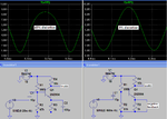
A "common emitter" transistor amplifies voltage up to about 240 times but without negative feedback it has horrible distortion at high output levels. Here is a simulation of a common emitter transistor without negative feedback and also with some negative feedback provided by a series emitter resistor. The negative feedback reduces the voltage gain and reduces the distortion.
 

Attachments

  • sim transistor distortion1.PNG
    sim transistor distortion1.PNG
    34.2 KB · Views: 195

Hi Audioguru,

The negative feedback u using is series emitter resistor or Negative feedback amplifier?

Regards,
YY
 

The negative feedback u using is series emitter resistor or Negative feedback amplifier?
What is a "negative feedback amplifier"? Almost ALL amplifiers use negative feedback to set an accurate voltage gain and reduce distortion.

My transistor uses R3 as its series emitter resistor and when it does not have a capacitor in parallel with it then it produces negative feedback that reduces the voltage gain to a little less than Rc/Re which is 10k/1k (10).
The input is 460mV peak and the output is about (9.5V - 1V)/2= 4.25V peak so the voltage gain is 4.25/0.46= 9.24 times.
 

There are three modes of transistor. 1) Cut off 2) Saturation 3) Active
First two modes are used in switching applications.while Active Mode is used in amplifications.Now there are three configurations you can use it as an amplifier. 1) Common Emitter 2) Common Base 3) Common Collector
Common Emitter has large Voltage and Current Gain.while Common Base has large Voltage Gain but Current Gain is approximately 1.And Common Collector is Voltage Buffer with High Current Gain.
 

Status
Not open for further replies.

Similar threads

Part and Inventory Search

Welcome to EDABoard.com

Sponsor

Back
Top