Continue to Site

Welcome to EDAboard.com

Welcome to our site! EDAboard.com is an international Electronics Discussion Forum focused on EDA software, circuits, schematics, books, theory, papers, asic, pld, 8051, DSP, Network, RF, Analog Design, PCB, Service Manuals... and a whole lot more! To participate you need to register. Registration is free. Click here to register now.

BGT24ltr11 compensation structure is matching at 100 ohm and not 50 ohm?

Status
Not open for further replies.

Georgy.Moshkin

Full Member level 5
Full Member level 5
Joined
Oct 9, 2017
Messages
271
Helped
44
Reputation
88
Reaction score
39
Trophy points
28
Activity points
2,526
According to this documents
https://www.infineon.com/dgdl/Infin...N.pdf?fileId=5546d462576f34750157d231ba29723d
https://www.infineon.com/dgdl/Infin...N.pdf?fileId=5546d4625696ed7601569d2ae3a9158a
bgt24ltr's TX load impedance and RX input impedance is 50 ohm (Including RX port matching structure according to AN472)
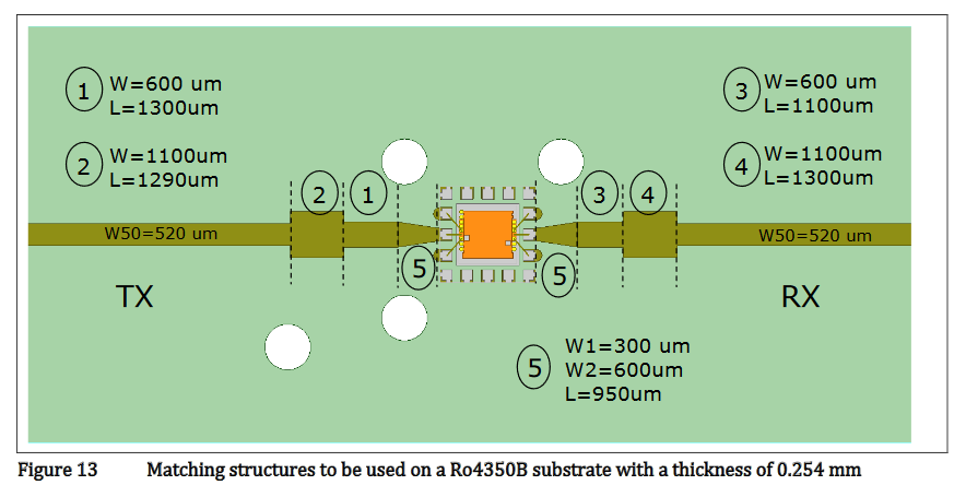
When I am using FDTD simulation of microstrip structure perfect matching only occurs if mmic ports are set to 100 Ohm (tapered part "5").
Is it correct to assume that pin impedance is 100 Ohm and purely real if i want to design other matching structure, or directly use 100 ohm microstrip line?
attachment.php

bgt24ltr.png
 

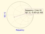
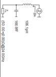
the portion 2 have some reactance so you cannot use real value component. If you have the PCB then find out the impedance at the pin by placing one pi at chip and one at SMA connectorsmith.PNGschematic.PNGimpedance.PNG
 
According to this documents
https://www.infineon.com/dgdl/Infin...N.pdf?fileId=5546d462576f34750157d231ba29723d
https://www.infineon.com/dgdl/Infin...N.pdf?fileId=5546d4625696ed7601569d2ae3a9158a
bgt24ltr's TX load impedance and RX input impedance is 50 ohm (Including RX port matching structure according to AN472)
When I am using FDTD simulation of microstrip structure perfect matching only occurs if mmic ports are set to 100 Ohm (tapered part "5").
Is it correct to assume that pin impedance is 100 Ohm and purely real if i want to design other matching structure, or directly use 100 ohm microstrip line?
attachment.php

View attachment 152087

Sounds about right but if you want to be more precise, you can use smith chart. I had a bit of reactance and real part was higher than 100Ω.
 
usx said:
Sounds about right but if you want to be more precise, you can use smith chart. I had a bit of reactance and real part was higher than 100Ω.
Did you used this MMIC? I am using substrate different from ro4350 and my design uses non-50Ohm lines for most part.

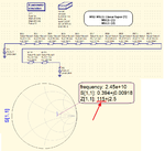
If we go from 50 ohm line W50 through line (2) -> (1) -> (5), after linear taper around 100 Ohm with small complex part. Linear tapper approximated by ten 0.1mm lines MS2-MS11:
bgt24qucs12.png

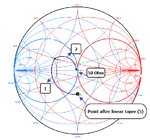
If pin impedance is set to 100 Ohm, then FDTD analysis of linear taper (5) alone results in complex impedance, which almost perfectly transforms to 50 ohm using lines (1) and (2):
bgt24smith.png
Note: "point after linear taper" is point between (1) and (5), not MMIC pin. This point impedance is entered manually based on impedance from FDTD simulator.

So it seems that MMIC pin impedance almost purely real 100 ohm. Performing same matching with quarterwave transformer will require single 0.27mm x 1.89mm line, Maybe recommended matching somehow minimizes transition effect near IC to get better matching. I will post additional information after testing prototype with other matching configuration assuming 100 ohm pin impedance.
 

I've used MOM simulator to analyze this matching structure and it showed a reactive component in addition to real 110Ω impedance. I'll look through my files and attach a setup here later today.
 
According to my simulation using ADS Momentum, output impedance was 100-34j Ω. I made assumption that it will not change if I change dielectric thickness, and I scaled their matching structure to match 100-34j at different thickness (we use 20 mil instead of 10 mil). We got the boards today and I measure TX power at -2 dBm instead of +6 dBm. Can impedance of IC change with dielectric thickness?

This thread is for reference:
https://www.infineonforums.com/threads/5890-TX-and-RX-port-impedance-of-BGT24LTR11N16
 
Last edited:
usx, what was your model, what Er value did you used in ADS? Only sections (2)-(1)-(5)?

Here is my recent result from finite element code run with pretty dense grid
parameters: er=3.66 , h=0.25 mm (ideal substrate, PEC + PML)

frequency = 24.000 GHz
Z0=50;
S11=0.306-0.065*i;
Z11=Z0*(1+S11)/(1-S11)
Z11 = 92.8- 13.4*i

port 1 (before taper) is set to 50 ohms, and it sees 92.8 Ohm. not sure if it is correct. At least this code gives good values for single patch. But metal layer i use is very thick.

I think fastest solution is to make prototype board with stepped sizes (5 steps).
Or use other matching structure, for example open-ended stub, which could be tuned by cutting. And after good result is obtained redo the simulation.

From simulation i have noticed that tapered part (5) is kind of sensitive to ground metal near ic, and maybe answer is that it more like a grounded coplanar waveguide at ic end.
 

port 1 (before taper) is set to 50 ohms, and it sees 92.8 Ohm. not sure if it is correct. At least this code gives good values for single patch. But metal layer i use is very thick.

Port 2 is known to be 50 Ohm, port 1 is unknown it is not "set to 50 ohms"; it can be set to 100 ohm or 200 ohm. If port 1 is before taper (connected to MS2 on your setup), then it sees 93-13j looking towards antenna. If you change your port 1 impedance to 93-13j, your circuit will be matched. If you set impedance of port 1 to 200 ohm, you'll see Z0*(0.465+j*0.067) = 93-j*13.

I got my numbers in the ballpark and circuit board we got back is missing 6-8 dBm of power. I can't figure where it went.


Do you measure frequency of operation? for example using spectrum analyzer or prescaler output pin.
 

Do you measure frequency of operation? for example using spectrum analyzer or prescaler output pin.

Yes, spectrum looks clean, there's one CW tone, problem is with power.
 

Status
Not open for further replies.

Part and Inventory Search

Welcome to EDABoard.com

Sponsor

Back
Top