Continue to Site

Welcome to EDAboard.com

Welcome to our site! EDAboard.com is an international Electronics Discussion Forum focused on EDA software, circuits, schematics, books, theory, papers, asic, pld, 8051, DSP, Network, RF, Analog Design, PCB, Service Manuals... and a whole lot more! To participate you need to register. Registration is free. Click here to register now.

Best way to supply LED

Status
Not open for further replies.

Yoshidk

Newbie level 6
Newbie level 6
Joined
Oct 27, 2011
Messages
14
Helped
0
Reputation
0
Reaction score
0
Trophy points
1,281
Activity points
1,393
Hello all!

I have a circuit with 20 White LEDs, which change with time controlled from a µC and transistors, 3 to 6 of these are ON at the same time
From the LED-datasheet i read:
"Forward Voltage 3.3V"

My circuit supply is 12V, so normally i would serie connect the LED with a resistor to make 3.3V across the LED, but im thinking this would burn too much power if the LED are constantly on..

Should i regulate the voltage to 3.3V, or limit the current after each LED, or what is the most power effective way to supply these LEDs?
(I can sketch the schematic if other stuff are important)

Thank you
 

Sure, this would illustrate my circuit, though i have 20 outputs to control transistors, and in some of the transistors there are 2 LEDs..
DC forward current = 30mA
wordclock.png
 

First of all I would replace these Darlingtons with low Rdson FETs. Second of all if you need to control each LED/pair of LED individually then you should use a DC/DC converter to reduce 12V to 3.3~3.5V.
 

What is the advantage from Rdson FET compared to darlingtons?
The reason i chose those, were i had access to an IC array, so i could easy place 3 of these instead of 20 singles..

You mean regulate the current with a voltage regulator like: LM317 ?

Thank you
 

What I meant was FETs with low Rdson - low drain source resistance. The advantage is they have very low on resistance compared to BJTs therefore you waste less energy and second of all they are faster than Darlingtons so implementing PWM should not be a problem. Third reason and this one is not clear cut is that darlingtons are very sensitive and noise in your circuit may be enough to turn them on at least intermittently.

DC/DC converter is not a regulator. Regulators like LM317 reduce the voltage and keep the current constant. So if you want to have 3.5V 600mA you need to provide 12V 600mA at the input. As you can see the efficiency is only 29%. The excess energy is dissipated as heat. For your application they are no better than resistors in series.
DC/DC converter will reduce 12V to 3.5V with approximately 75 - 80% efficiency. To get 600mA/3.5V you will only need ~220mA/12V on the input.
 

Oh like a DC/DC stepdown converter? That seems both costly and are way too large fit anywhere in my setup..

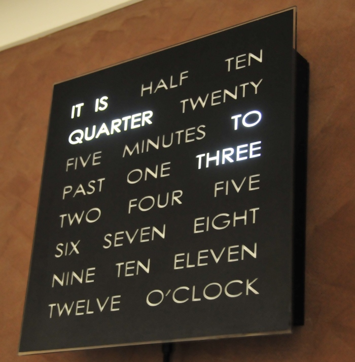
Actually im trying to make this wordclock:
vinylclock.jpg


And i have programmed my ATmega16 to switch the 24 outputs for LEDs
The VCC on µC is 5V, and i just had a 12V DC supply at hand so i thought to use that, but i guess i should search for a 5V supply instead and just use resistors for the LEDs.. Unless there is some other simply solution im not seeing?

Thank you
 

What I meant was FETs with low Rdson - low drain source resistance. The advantage is they have very low on resistance compared to BJTs therefore you waste less energy and second of all they are faster than Darlingtons so implementing PWM should not be a problem. Third reason and this one is not clear cut is that darlingtons are very sensitive and noise in your circuit may be enough to turn them on at least intermittently.

DC/DC converter is not a regulator. Regulators like LM317 reduce the voltage and keep the current constant. So if you want to have 3.5V 600mA you need to provide 12V 600mA at the input. As you can see the efficiency is only 29%. The excess energy is dissipated as heat. For your application they are no better than resistors in series.
DC/DC converter will reduce 12V to 3.5V with approximately 75 - 80% efficiency. To get 600mA/3.5V you will only need ~220mA/12V on the input.
I must disagree with all three of your reasons in this particular application. First there is the issue of wasted power. This is not a concern here because the power must be wasted somewhere - either in the dropping resistors or in the switches. It does not matter where. If the OP really wanted to take into account the higher Rds-on of Darlingtons he could simply use lower dropping resistors, and therefore reduce the power wasted there by the same amount as the extra power being wasted in the switches.

Then there is the issue of speed. Yes, Darlingtons may be slower switches. But they are fast enough to PWM LEDs fast enough to make the switching unnoticeable.

The issue of noise should not be a concern when the bases are being driven directly from a local uC.

However I agree completely that DC-DC converters offer the only hope of improving energy efficiency in this application.

- - - Updated - - -

Oh like a DC/DC stepdown converter? That seems both costly and are way too large fit anywhere in my setup..

And i have programmed my ATmega16 to switch the 24 outputs for LEDs
The VCC on µC is 5V, and i just had a 12V DC supply at hand so i thought to use that, but i guess i should search for a 5V supply instead and just use resistors for the LEDs.. Unless there is some other simply solution im not seeing?

Thank you
Yes, a 5-volt supply is both efficient and simple to use, if it is available.
 

I must disagree with all three of your reasons in this particular application. First there is the issue of wasted power. This is not a concern here because the power must be wasted somewhere .... CUT......

If he uses 3.3V from a switcher then no extra energy needs to be wasted and no extra heat generated and that's why low Rdson of FETs could come in handy.

Then there is the issue of speed. Yes, Darlingtons may be slower switches. But they are fast enough to PWM LEDs fast enough to make the switching unnoticeable.

Probably completely irrelevant for this application anyway.

The issue of noise should not be a concern when the bases are being driven directly from a local uC.
.
fast digital device and unknown layout - the noise will always be a problem
 

Looking at the circuit, you are supplying 5V to the uC so why not use the 5V to supply the LED's too? If your transistors have an on resistance that will give a 1.7V drop, then you do not need resistors (5-3.3=1.7).
A single supply would be cheaper for you. And as you are only turning the LED's on or off at each time change, you do not need to worry about PWM etc.
 

Status
Not open for further replies.

Similar threads

Part and Inventory Search

Welcome to EDABoard.com

Sponsor

Back
Top