Vermes
Advanced Member level 4

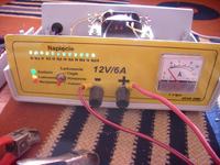
This device was designed in 2006 and it is a basic rectifier.
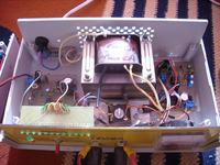
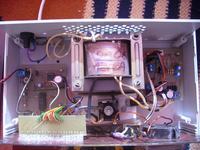
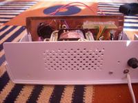
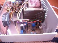
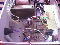
The transformer is TS 70/5 from an radio “Amator 2”. The secondary winding was wound again to get: 13V – about 50 coils of an double wire that gives 27V, auxiliary voltage 13V – double wire from an old coil.
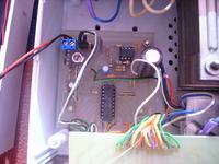
The analogue voltmeter has 12 LEDs. It's based on UAA180 – it was taken away from an old car – a Trabant or a Wartburg.
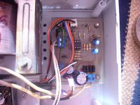
The loading system in based on a so-called window comparator (circuit from EdW + some changes). The main task of this module is to control the relay (a small, rated to 10A contacts from Ford Escort).
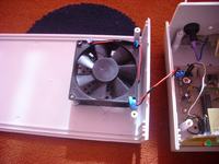
The fan driver switches a silent fan (with an bearing from and old AT power supply). As a temperature sensor 4 diodes (1N4148) connected in series were used – it gives 10mV/C voltage change. The switching threshold was set to about 40 deg C – therefore, the fan switches on very rarely.
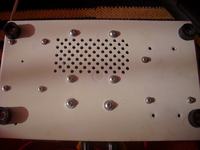
The housing is Z series. The front panel was designed in Corel 9 and printed on a yellow self-adhesive paper covered by adhesive film.

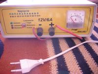
The rectifier has 3 modes:
- automatic loading - the loading starts when an accumulator is connected and when the voltage is bigger than 10V. It stops when the voltage reaches 15V
- no loading – (the switch in the middle position) – useful for reading the current voltage of the accumulator
- continuous loading – there is always tension on the clamps, whether there is an accumulator connected or the voltage is in 10V to 15V
The larger the accumulator capacity is, the greater the initial charging current is. The biggest current is 6A. On the end of loading, the circuit periodically switches on and off, which appears as clicking of the relay.
Link to original thread and some useful attachments - Prostownik by HSWG