Continue to Site

Welcome to EDAboard.com

Welcome to our site! EDAboard.com is an international Electronics Discussion Forum focused on EDA software, circuits, schematics, books, theory, papers, asic, pld, 8051, DSP, Network, RF, Analog Design, PCB, Service Manuals... and a whole lot more! To participate you need to register. Registration is free. Click here to register now.

[SOLVED] basic LC oscillator - basic question about its operaiton

Status
Not open for further replies.

palmeiras

Full Member level 6
Full Member level 6
Joined
Feb 22, 2010
Messages
375
Helped
61
Reputation
122
Reaction score
50
Trophy points
1,308
Location
South America
Activity points
4,199
Hello guys,

Could you, please, help me understading the basic LC oscillator?
1-Who does it works?

2-If a voltage pulse (not oscillation) is inject in node X, will this circuit oscillate?

3- Is there any text showing a step-by-step sizing process?

Thank you very much,
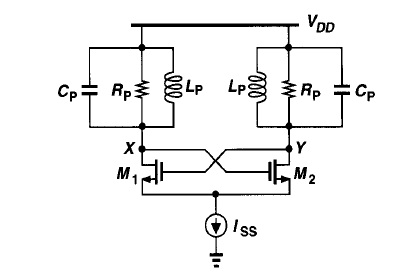
32_1329963764.jpg
 

I make a hobby of trying different oscillator circuits on my homebrew simulator.

I've never seen this configuration. It's sort of a novelty oscillator. The LC oscillators I've seen only have one tank circuit.

I find it will work using my own simulator.

The two tank circuits can be made from dissimilar values. They wind up working in sync, regardless.

A 'shock' of any kind is often sufficient to get an oscillator going. I usually do it by turning off a wire momentarily. However the circuit must be able to oscillate in the first place.

I'm using transistors rather than mosfets. It is necessary to put resistors in the bias wires.

I substituted a resistor for the bottom component which looks like a current source.

M1 turns on and M2 shuts off, when node Y becomes higher than X. This immediately pulls current through the left-hand coil.

M2 turns on and M1 shuts off, when node X is higher than Y. This immediately pulls current through the right-hand coil.

The tank circuits show an oscillating effect, although it is not at their resonant frequency. The coils carry DC (downward) most of the time. However one coil will briefly have current flowing upward momentarily through it, when its transistor is off.

Then the transistors switch state, and the other coil has current flowing upward through it briefly. The capacitors appear to influence the action only slightly. Current direction through the capacitors can switch direction with no apparent regard for what the coils are doing.

So now I am simulating it after removing the capacitors and resistors. As it turns out, the capacitors are not essential. The coils alone will exhibit alternating choke action.

But do not take my word for any of this.
 
Hi,

Initially, if we give pulse at point 'X' it will turn ON M2 and capacitor Cp (right side) gets charged for a time equal to pulse duration. After, the electrostatic energy stored in capacitor will be discharged through inductor. After capacitor is fully discharged, indutor will oppose this sudden change in current and discharge the energy to charge capacitor again. this process continues to produce oscillations(decays exponentially). but here, the oscillations due to Cp and Lp in right will turn ON M1 which makes circuit in Left to operate. Cp and Lp in Left start to oscillate which in turn trigger M2. So, this process is cumulative and we will get sustained Oscillations.

Am i right??? Correct me if I'm wrong.

If no power supply were connected, and a single pulse were sent to point X, then it would trigger ringing cycles as you describe. X node would show swinging volt level. (This is the effect which sustains oscillations in a 1-tank oscillator.)

However with power applied, tank oscillations are overwhelmed (for the most part) by supply current going through the coils.

Resonance can indeed be seen operating in each tank loop. Particularly in the loop with the higher resonant frequency. That loop has a chance to go through a ringing cycle or two. Current can be observed reversing direction.

However the tank loop with the slower frequency can only manage one ringing cycle at a time. Coil current climbs, and at the time when the coil has least volt drop, that creates the high node. The transistors switch state. Hence the slower tank loop determines the moment when the transistors switch on and off.

My simulator shows that when power is removed, both of the tank loops ring independently, until oscillations decay.

I hope to be able to make a video animation of this circuit, to put on Youtube.
 
This same oscillator is examined in an article found through an online search.

ANALYSIS OF EMITTER DEGENERATED LC OSCILLATORS USING BIPOLAR TECHNOLOGIES

The link below is to the pdf article. If it is not clickable then the link will be found via a search on the above title.

http%3A%2F%2Fciteseerx.ist.psu.edu%2Fviewdoc%2Fdownload%3Fdoi%3D10.1.1.83.4883%26rep%3Drep1%26type%3Dpdf&ei=vg9HT-anJ4SDsgKEjeXqCA&usg=AFQjCNHeg3Gesln3CzlPFa6FUoRhNBhC-A
 
Here is the link to my Youtube video which portrays the workings of this oscillator.

I should add a 'spoiler alert'. It could be more fun to try to figure out beforehand what happens. There is a lot going on here.

The final 30 seconds is shown with power removed. The tank loops can be seen ringing independently.

Cross-coupled dual RLC oscillator (Animated) - YouTube
 
This is a figure from one of Razavi's textbooks, why not actually read the book?

Hello guys,

Could you, please, help me understading the basic LC oscillator?
1-Who does it works?

2-If a voltage pulse (not oscillation) is inject in node X, will this circuit oscillate?

3- Is there any text showing a step-by-step sizing process?

Thank you very much,

32_1329963764.jpg
 
Hello BradtheRad!!! I have just checked your video! It is amazing!!!!!

Thank you very much for posting it. I’ll watch it again. It is starting to be clear its operation now… Please, don’t delete it yet. :)
I'll come back!

best regards, and thanks again!
 

Status
Not open for further replies.

Part and Inventory Search

Welcome to EDABoard.com

Sponsor

Back
Top