Continue to Site

Welcome to EDAboard.com

Welcome to our site! EDAboard.com is an international Electronics Discussion Forum focused on EDA software, circuits, schematics, books, theory, papers, asic, pld, 8051, DSP, Network, RF, Analog Design, PCB, Service Manuals... and a whole lot more! To participate you need to register. Registration is free. Click here to register now.

Autonomous ESP8266 POST data via WiFi to the MongoDB server. GET graphs anywhere.

Status
Not open for further replies.

alexanderkif

Newbie level 4
Newbie level 4
Joined
May 7, 2020
Messages
6
Helped
0
Reputation
0
Reaction score
0
Trophy points
1
Activity points
50
Hi.

You can use your sensors, but again I made a weather station :).

scema-min.png

The board starts, sends data to backend (Node.js) and falls asleep for 5 minutes. To save battery power, the field effect transistor at pin D6 turns off the power to the BME280. The 18650 battery is controlled by input A0. If the battery voltage exceeds 4.2V, the D7 output breaks the battery charge circuit from the solar panel.

alg.png desktop-tv.png mobile-vert-lg.png

Out of the door:

20200507_103241.jpg 20200507_103250.jpg 20200507_103350.jpg
20200507_104031.jpg 20200507_104043.jpg


Have you considered the voltage polarities between pins on the BME280 when it is 'powered down' ?

Brian.
 

Hi Brian.
No. But I measured right now.
VIN, SCL, SDA 3.2V.
GND 2.6V and slowly decreasing.

Aleksandr.
 

I think you need an oscilloscope to check. The problem with 'disconnecting' the ground side of a module while leaving signal lines and power connected is the supply return path might be through the signal lines or one signal line might provide power and return it through another. It will almost certainly result in reverse polarities across the pins and could cause damage or latch-up when power is reapplied.

Brian.
 

Hi Brian.

I do not have an oscilloscope.
I controlled the battery voltage value. When I put this mosfet, the battery began to discharge more slowly.
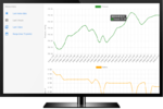
My station has been operating since January, but according to statistics, nothing is damaged. You can see the graphs at
https://alexanderkif.github.io/meteo-front
Maybe I'm doing something wrong, but it works.

Aleksandr.
 

You might get away with it but technically it might violate the ratings. What you have to consider is the voltages on the BME280 pins have to be positive with respect to the GND pin and negative with respect to the Vin pin. If you raise (or allow it to raise) the GND pin voltage and either or both the I2C pins go low, they will be negative with respect to the GND pin. I'm not sure what protection is internal to the BME280, it may be enough to prevent damage from the reversed voltage but there is a further risk that the circuitry behind the pin may 'latch up' and draw a high current when the GND pin goes back to 0V again.

It isn't generally a good idea to disconnect the ground side of any device that has other driven lines feeding it but you can go some way to protecting it if you can ensure the SCL and SDA lines are both driven high before you turn the MOSFET off. Make sure you turn the MOSFET back on first before driving SDA or SCL low again. It might be a good idea to add a resistor across Vin and GND to 'tie' them loosely together when the device is powered down. I would suggest a 100K resistor, that should be low enough that GND doesn't float but not add any significant load to the battery.

Brian.
 

Hi Brian.

Can I power the sensor directly from the output pin (without MOSFET)?
Will this be the correct scheme?
In this case, the sensor will sleep with the microcontroller.
The maximum current that can be drawn from a single GPIO pin is 12mA.
Operating current BME280 is 0.4mA.

pinout.png
 

Yes, you can do that but I would still be careful to drive the outputs to a safe state before putting the ESP8266 to sleep. In sleep mode, the processor is halted to save power but the pins remain in the same state so if you drive them all low before sleeping you can be sure none of them can still be sourcing current.

Brian.
 

Hi Brian.

After your comments, I looked at the specifications and found the following: SDA and SCL are not pure open-drain. Both pads contain ESD protection diodes to VDDIO and GND.
See the screen in the attachment.
Re-polarity cannot damage the device, as there is protection. I think it makes no difference to switch Vin or GND of the board.

protection.png
 

The reason I urged caution is that those internal ESD diodes are there to protect the device from occasional ESD spikes but not for continuous use with reverse polarity. Yes, it will work but you are using the device outside specification by relying on it's protection diodes for normal operation.

Crash barriers are there as a precaution, not so you don't have to use brakes!

Brian.
 

Hi,

Re-polarity cannot damage the device, as there is protection.
As most CMOS ICs it has ESD protection diodes.
But they are designed for ESD pulses, only rarely occurring pulses of very short time.
They usually are not meant for steady currents.
In either case you need to keep on datasheet specifications. If it allowes to draw DC current of the ESD diodes, then you may do so.
Usually datsheets tells something like "port pin voltage must not exceeed VCC +0.3V" or so ... to prevent the diodes to become conductive.

Power down consumption.
As Brian mentioned the ports keep state at power down.
Check every IO whether you want it LOW or HIGH, don't let them floating.

I2C pullups
If the sensor is your only I2C device, then you may connect the pullups to the same port that powers the sensor.
Thus during power down the pullups are switched OFF, too.

Klaus
 

Will the pullup resistors solve the problem?
Here is my version of the board:

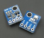
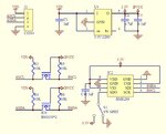
GY-BME280.jpg GY-BME280-SCH.jpg

The circuit has pullup resistors.
 

Hi,

after post#12 I reviewed some datasheets.

now some questions arise:
* Why cut off power to the sensor?
Current consumption? --> The sensor has a 0.1uA sleep mode. Why not simply use this feature?

* why the level sihifting on the SCL and SDA lines?
AFAIK the levels of the ESP8255 are 0V/3.3V --> If so, no level shifting necessary.

Klaus
 

Hi,

* why the level sihifting on the SCL and SDA lines?
AFAIK the levels of the ESP8255 are 0V/3.3V --> If so, no level shifting necessary.
Klaus

the level shifter is most likely implemented as those boards are intended to be used (and advertised) in combination with an arduino with a logic high level of 5 V.

greets
 

Status
Not open for further replies.

Similar threads

Part and Inventory Search

Welcome to EDABoard.com

Sponsor

Back
Top