Continue to Site

Welcome to EDAboard.com

Welcome to our site! EDAboard.com is an international Electronics Discussion Forum focused on EDA software, circuits, schematics, books, theory, papers, asic, pld, 8051, DSP, Network, RF, Analog Design, PCB, Service Manuals... and a whole lot more! To participate you need to register. Registration is free. Click here to register now.

Automotive reverse polarity

Status
Not open for further replies.

Rajinder1268

Full Member level 3
Full Member level 3
Joined
Mar 20, 2021
Messages
162
Helped
1
Reputation
2
Reaction score
4
Trophy points
18
Activity points
1,228
Hi all,
I am using 12V from a car battery to power electronics. The current consumption of my circuit is 1A max, however it will run closer to around 850mA.

I need to add reverse polarity protection to my circuit.
I have opted for a simple Schottky diode solution, as I am limited for PCB space and it has a forward voltage of around 0.5V.

A car battery can spike to negative and positive voltages due to load dump and inductive loads.

I am looking to select a diode with a VRRM of 60-100V, forward surge current of 30A. Average current of 2A.

Is there anything else that I need to consider or have overlooked?
 

Hello Rajinder, I recommend look at the this blog,
Basically it is enough you attention "peak current and voltage". Also don't forget the TVS diode option for voltage spikes.
 

Hello Rajinder, I recommend look at the this blog,
Basically it is enough you attention "peak current and voltage". Also don't forget the TVS diode option for voltage spikes.
Thanks for the link. I do have a TVS before the reverse polarity diode and a fuse.
Was not sure of the reverse repetitive voltage and surge current that I need. My thoughts were that the fuse would open circuit for surge and a TVS will handle spikes.
--- Updated ---

I have had a look at the link. I have selected a STPS2150A as a preliminary choice.
This has a average forward current of 2A, 75A surge and 150V VRRM.

Does the forward average current derate at lower and higher temperatures?
 
Last edited:
STPS2150A

Does the forward average current derate at lower and higher temperatures?
Hi,

- 'derate at lower temperatures'? Unlikely, it's a PN junction. It just should be a tiny bit slower than at Tamb 25°C or Tamb max.

- Phew, I'm exhausted, I had to search for the datasheet, STMicro's came up first, then I had to actually bother to read the datasheet as well, and finally, on page three I found figure 2. I need a long rest now after making such an effort.

I could have saved myself the expenditure of using my calories doing the job for you and just said that it's a diode, of the PN junction family, so common sense says it most likely follows the straight line to +70°C and then slopes downwards to (0 current * 0 voltage) at x temperature limit.

I could also have answered with: 'Does a bear (bleep) in the woods?'

:)
 

Hi Rajinder,

I stand corrected about PN junction - linked article says Schottkys are not PN but usually an N + metal junction. Derating comment(s) still valid, as datasheet graph in figure 2 shows.


The typical protection needed in an automobile environment is reverse polarity. The car's battery is normally disconnected during maintenance or service.

reconnected, and There is a chance that they will connect.

the improper battery terminals with the wires. This mistake

can be dangerous and harm electronic component

unit of control. There is a way to prevent these damages.

protection from reverse polarity is required. Schottky transistors

will lose a lot of power. LM5050-1-Q1 together with

N-channel MOSFETs may be utilised to decrease the

dissipation of power.
 

Hi,

(I guess you meant "schottky diodes" instead of "schottky transistors")

Generally true.
But in the case of 850mA ... there are schottky diodes with less than 400mV voltage drop.
With maybe 350mW of power dissipation..

Diode manufacturers as well as distributors usually provide interactive selection tools.

Klaus
 

Hi
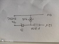
I have attached the circuit protection.
The fuse is rated at 3.7A, MF-LSMF185/33X2 hold current of 1.85A, which drops to 0.85A at 85C.
The TVS is bidirectional SMC3K24CAHM5/57 this has a working voltage of 24V, clamping at 38.9V.
The diode is SBR2M60S1-F, has low VF.
The idea was that the TVS clamps any voltage higher or lower than 38.9V to protect my DCDC which operates at max input of 42V.

I want to test this actually is the case. Would I be able to put 60V into just this circuit and reverse it (with no DCDC) connected? Or is there a better way of testing the operation of the Fuse/TVS and diode circuitry? Or will any voltage above 38.9V result in smoke?
 

Attachments

  • IMG_20220822_113821.jpg
    IMG_20220822_113821.jpg
    1.6 MB · Views: 167

Hi,

In a reverse polarity event of 60V, how much current would pass through the TVS, it wouldn't surpass Pd limit? If idea is to blow fuse, I think it will work, fwtw.
 

The fuse is OK for test/hobby projects, but not for mass produced automotive electronics.
For mass production, the unit must automatically return to normal operation after the overload situation (if it is within specified limits). Normally, the load dump is the most difficult case, except for low current units where a series resistor can be use before the TVS diode, instead of a fuse.

For higher current units, a solution like the Maxim MAX16128/MAX16129 can be used, but it is possible to implement the same technique with a bunch of discrete components.
 

    d123

    Points: 2
    Helpful Answer Positive Rating
The fuse is OK for test/hobby projects, but not for mass produced automotive electronics.
For mass production, the unit must automatically return to normal operation after the overload situation (if it is within specified limits). Normally, the load dump is the most difficult case, except for low current units where a series resistor can be use before the TVS diode, instead of a fuse.

For higher current units, a solution like the Maxim MAX16128/MAX16129 can be used, but it is possible to implement the same technique with a bunch of discrete components.
Thanks for the information. This is a prototype solution which will be tested in automotive applications i.e. using a car battery etc. The idea was to have the TVS clamp any transients, getting to the DCDC converter. Provided the fault condition is not too long, in theory it should return back to its normal state. How could I implement a similar solution to the MAX16128 using discrete components?
 

Status
Not open for further replies.

Similar threads

Part and Inventory Search

Welcome to EDABoard.com

Sponsor

Back
Top