Continue to Site

Welcome to EDAboard.com

Welcome to our site! EDAboard.com is an international Electronics Discussion Forum focused on EDA software, circuits, schematics, books, theory, papers, asic, pld, 8051, DSP, Network, RF, Analog Design, PCB, Service Manuals... and a whole lot more! To participate you need to register. Registration is free. Click here to register now.

Auto on switch after power failure

Status
Not open for further replies.

badboydas

Newbie level 5
Newbie level 5
Joined
Feb 16, 2008
Messages
8
Helped
0
Reputation
0
Reaction score
0
Trophy points
1,281
Activity points
1,335
Hi All
Hope one of you clever people can help. I have a HDMI switch in the loft connected to a UPS, every time there is a long power cut and the UPS cuts out the unit does not switch back on, unless I go up in the loft and push the momentary switch(what a pain). Opening the unit shows a tactile switch, putting a meter across the switch shows 0volts when the switch is pressed and released there is a constant 2.31volts. I`m pretty sure this could be completed with a transistor and a couple of resistors but my electronics sucks.:)
cheers
 

It probably will not work if you install a short across the switch (which would only need a resistor to do). If that could do it, then there is no need for the switch in the first place.

I think the unit turns on only after you let up the switch after pressing it down.

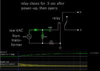
A solution would be to install a relay across the switch.
The relay is activated by a circuit which comes on for a fraction of a second after mains power returns.


The diode and capacitor pass current for a short time, until the capacitor is charged up.

The 100k resistor discharges the capacitor during a blackout, so the circuit is ready to operate when power resumes.
 
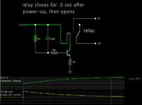
I like the circuit Brad!, i would actually use a transistor to drive the relay and capacitively the base to the units +Vcc line, same thing but no extra transformer. Easiest way, is to wire the relay in the loft to the switch and power it downstairs from a "wall wart" PSU.
Frank
 
Thanks guys
the tranny for the HDMI switch is external, input is 12v 5A so I can tap of that. Bradtherad I think you got It, correct me if I`m wrong remove the diode from your circuit solder directly from the input? Chuckey can you eleborate with a sketch given that I can tap into the regulated switch mode supply (off the pcb). Forgive me for checking out both of your inputs, but I need simply but effective.
cheers
Darren

- - - Updated - - -

Thanks guys
the tranny for the HDMI switch is external, input is 12v 5A so I can tap of that. Bradtherad I think you got It, correct me if I`m wrong remove the diode from your circuit solder directly from the input? Chuckey can you eleborate with a sketch given that I can tap into the regulated switch mode supply (off the pcb). Forgive me for checking out both of your inputs, but I need simply but effective.
cheers
Darren
 

Nice one Bradtherad, :)
cheers
Darren
 
Last edited:

Nice one Bradtherad, Would that be a PNP or a NPN general purpose transistor. forgive my ignorance:)
cheers
Darren

NPN. The arrow points in the direction of the PN junction. It points in the direction of current flow.

If you only have a PNP, then the schematic is easy to revise by mirroring it.

Component values may need adjusting, to get everything to work right.
 
Thanks Radthebrad
To be honest I just come back from the pub (grey cells went missing) As soon as I clicked post I knew how dumb I was:)
I`ll put it to the test later and let you know how it went.
cheers
 

Spot on Bradtherad and Chuckey
All up and running, nice job lads
Many thanks
Darren
 

Status
Not open for further replies.

Part and Inventory Search

Welcome to EDABoard.com

Sponsor

Back
Top