Continue to Site

Welcome to EDAboard.com

Welcome to our site! EDAboard.com is an international Electronics Discussion Forum focused on EDA software, circuits, schematics, books, theory, papers, asic, pld, 8051, DSP, Network, RF, Analog Design, PCB, Service Manuals... and a whole lot more! To participate you need to register. Registration is free. Click here to register now.

Audio Problem: LM833 Bridge amp serious instability (?) problem. Need Help :-(

Status
Not open for further replies.

userx2

Full Member level 3
Full Member level 3
Joined
Sep 19, 2008
Messages
177
Helped
2
Reputation
4
Reaction score
3
Trophy points
1,298
Activity points
3,092
Hello all.

Hope this is the right forum. I am a desing engineer (mostly digital) and I have a problem with an audio circuitthat I kinda designed.

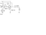
I have a bridge amplifier using BD139-16 and BD140-16 (see simplified rough pic).
It's part of a bigger system and we have made 50 of these. They were all kinda fine when testing the distortion with an AP (audio processor).

Now, another larger batch was made and ALL of them have huge distortion when testing on the AP. :cry:

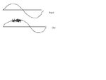
I looked into it today with a signal generator and oscilloscope and I found that the output stage (Headset load = ~100 Ohm) seems to burst into a VERY (YES VERY)!! high fequency oscillation at a certain level and fequency of input. I have attached a rough sketch of what I get on the scope. The osillation is visible in the top half of the output waveform.

I have tried everything I can think of and so has my collegue. We are not able to solve it at this stage and we are desperate.
The oscillation frequency is actually 69.65MHz (!!!!!!!)
It all ocuurs suddenly when the sine peak reaches around ~1V.

Removing the BD140 transitor solves the problem but then of course, I can't drive the full voltage swing required.
Removing the BD139 makes not much difference.

Touching anything (the op am poutput etc) with a 10:1 scope probe, changes the output waveform and it changes the level at which the oscillations occurs.

Lowering the 47 R resistor by adding a 120R in parallel, stops the problem but again, does not allow for the full voltage swing, if lower impedance loads are used.

We have tried caps across the 27k, 47R, output to gnd (47mF gets rid of the HF part but then ther eis a step in the output wafeform). we have also tried various other caps and ideas but nothing helps.

How the heck can such a circuit oscillate at 70MHz???? We suspect the LM833 an that it may not be suitable for a bridge amp like this but then what is the alternative in 8 pin smd?
The Vcc rail is +30V.

As you can see, I just don't know - and I have supposedly have 25 years of experience in electronics. :shock:


Maybe some op-amp / audio / analog expert out there can point me in the right direction?


Best egards
X
 

Attachments

  • Bridge amp1.JPG
    Bridge amp1.JPG
    13.3 KB · Views: 110
  • Bridge amp2.JPG
    Bridge amp2.JPG
    10.6 KB · Views: 102

Re: AUdio Problem: LM833 Bridge amp serious instability (?) problem. Need Help :-(

your output stage have problem. goto find some good class AB output stage
 

Re: AUdio Problem: LM833 Bridge amp serious instability (?) problem. Need Help :-(

I believe I have found the instability cause. I think the problem is caused by the feedback in the output stage. I'll explain it with some math:

Your output stage gain is aproximatelly given by:

Vout / Vin = ( 1 / 47 Ω - gm) / ( 1 - (1 / 47 Ω - gm) ) "gm" is transconductance.

This is for a small signal analysis. Though your signals are not "small" the theory remains the same, it only implies greater error, which we can ignore for now. As you can see, the numerator and denominator are similar and aparetelly your gain should be:

gain ≈ 1

However you're dealing with a very high "gm" due to the high DC current and two things can happen from here:

1) the numerator ( 1 / 47 Ω - gm) changes from negative to positive (gm < 1 / 47 Ω) and instead of having negative feedback you start having positive feedback leading to instability.

2) the denominator ( 1 - (1 / 47 Ω - gm) ) approaches zero leading to x / 0 = ∞ which causes infinite (theoretical) gain

You don't see the oscillation all the time because "gm" varies a lot for large signals. As your input signal increases, so does the output current and therefore the "gm". Changing capacitors will make little changes.

gm = I / 0.025

My advice is, get rid of the feedback from the 47 Ω resistor, you probably don't need it. You already have another feedback. Or else, change the value of that resistor, but you'll problably still be near oscillation.
 

You don't show any power supply decoupling on your drawing.
I assume that there is a 100nF across the op-amp +V pin and ground, and some capacitor across the power rails?

Try putting a 10R resistor in series with a 0.1uF cap from the output to ground. (Zobal network).
 
Last edited:

70 MHz oscillation sounds like being brought up by the output transistors on their own without participation of the OP. Supply bypassing and compact design of the output stage may already help against it. Ultimately you should try individual series base resistors for both transistors. A good old boucherot cell at the amp output (emitter junction) may help as well.
 

Hello

Thank you for the help !!
Good things have been mentioned and I am looking into them right now.

I also have a ZObel type network consisting of the 22R and 47n capacitor near the output.
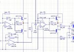
Of course I have decoupling etc. I have now attached a more complete part of the schematic.

The 47 Ohm resistor drives the output (headphone) during the time when the transistors are off.
Removing it, causes crossover distortion (since I do not have boas network in this case).

The interesting thing is that decreasing it seemd to improve things. I will have to conduct a few more experiments today to see.

Fact is that we made 50 of these and they worked fine and now, we have meade hundreds more and they do not work fine. I don't know what has changed.
Everything is smd and I use 0603 size parts for most components. the transistors and output caps are through hole parts.

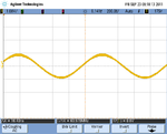
You can see the output of the first stage at the level just before the oscillation starts.
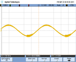
the second pic show the slightly increased level, showing the oscillation suddenly present near the bottom peak of the wave.

Best regards
X
 

Attachments

  • bridgeAmp1.JPG
    bridgeAmp1.JPG
    166.8 KB · Views: 101
  • scope_0.png
    scope_0.png
    42.1 KB · Views: 88
  • scope_1.png
    scope_1.png
    44.4 KB · Views: 89

Hello again.

Update:
Fcfusion is corret in stating that the 47R resistor is responsible.
I can cure the problem completey by removing the resistor.
Crossover distortion is unacceptable then.
I am now experimenting with different resistor values to find a compromise.

@Fcfusion - I don't fully understand where you get the formula for the Vo/Vi from.

Best regards
X
 

It's not particularly surprizing, that removing the 47 ohm resistor changes the circuit behaviour, as well it's clear why it's needed for the present circuit. Personally, I don't think that the feedback calculation hits the point. To make a transistor in common collector circuit oscillate, it's no sufficient to have a gm roll-off and a feeback less than unity. You'll need additional reactant circuit elements, either in the load or provided by wire and package inductances.

As another point, the 47 ohm resistor avoids cross-over distortions at low output level by bypassing the output stage, but the cicruit still involves non-linearities that will show up as only moderate THD numbers. A true class AB stage (with some bias current) performs considerably better.
 

@Fcfusion - I don't fully understand where you get the formula for the Vo/Vi from.

I've considered the output stage as a simple emitter follower amplifier, considering on of the transistors is always off, which is mostly true.

I_emitter = I_collector + I_base

I base = (Vin - Vout) / ( Rπ // R1)

Where Rπ is transistor input impedance, typically around 2kΩ for bipolar transistors, and R1 is the the 47 Ω resistor. We can aproximate this to:

I base = (Vin - Vout) / ( R1) because R1 << Rπ

I collector = - gm (Vin - Vout)

and now we have Vout = I emitter * RL where RL is your load.

Therefore

Vout = [(vin - Vout)/R1 + (-gm (Vin - Vout) )] * RL

Vout = (Vin-Vout)*RL ( 1/ R1 - gm)

Vout (1 - 1/R1 + gm) = Vin (1/R1 - gm)

Vout / vin = (1/R1 - gm) / (1 - 1/R1 + gm)

gm can vary a lot but considering the high DC current, it is generally several hundreds of mili Siemens

To make a transistor in common collector circuit oscillate, it's no sufficient to have a gm roll-off and a feeback less than unity. You'll need additional reactant circuit elements, either in the load or provided by wire and package inductances.

You don't need inductors for a circuit to oscillate. Lets not forget about RC oscillators. What the reactant elements do is generally switch phase until a negative feedback becomes a positive one. In this case there is already a potencial positive feedback without reactance elements. Once oscillating, the frequency is defined by the equivalent RC elements, including parasitic ones.

Anyway, thats just my opinion.
 

You don't need inductors for a circuit to oscillate.
You need with a loop gain below unity.

---------- Post added at 10:42 ---------- Previous post was at 10:27 ----------

Apart from the question of conditions to make a transistor oscillate, I was curious to find the fault in your calculation.

You calculate: ie = ib - ic = (vin - Vout)/R1 + (-gm (Vin - Vout)) = (1/R1 - gm)(Vin - Vout)

In other words, you find that the current through R1 (and parallel rb dynamic resistanceI and and collector current appearing at the emitter have opposite polarity. But this isn't true. They have equal polarity.

For a better understandable calculations, you should refer to the text book equations for common collector circuit.
 

As another point, the 47 ohm resistor avoids cross-over distortions at low output level by bypassing the output stage, but the cicruit still involves non-linearities that will show up as only moderate THD numbers. A true class AB stage (with some bias current) performs considerably better.

Hello
True and I know this but... I did experiments with the biased and unbiased versions during development and not a single person was able to tell the difference in sound quality. The biasing also had the side effect of allowing thermal runaway where both transistors eventually coocked themselves under certain conditions. Themal protection seemed necessary = more cost.
Since we needed the amplifier to be low cost, short circuit proof and rugged, I decided to remove the biasing again.
This is not for a Hi-Fi system but for a communications headset.
Also, I can't add anything much now.

I am still deciding if the resistor value change will solve this reliably enough t get it done to 100s of units.
Any other simple ideas I could try, are greatly appreaciated.

Best

x
 

You calculate: ie = ib - ic = (vin - Vout)/R1 + (-gm (Vin - Vout)) = (1/R1 - gm)(Vin - Vout)

In other words, you find that the current through R1 (and parallel rb dynamic resistanceI and and collector current appearing at the emitter have opposite polarity. But this isn't true. They have equal polarity.

Yes, I made a mistake with that current signal. LOL, I really though I had it figured out :p

Too bad. Anyway, I'm still puzzled how the 47 ohm resistor influences stability. With the corrected equation, that resistor should not cause oscillations.
 

Too bad. Anyway, I'm still puzzled how the 47 ohm resistor influences stability. With the corrected equation, that resistor should not cause oscillations.
I agree. The resistor alone can't cause it. There are several parameters involved like the OP output impedance, the transistor package parasitics, the wiring inductance and mutual coupling, and the load.
 

Latest Update:

Hello Folks, I have news.

It is the Op amps!!

I have established that the 1st batch of units we made used OnSemi LM833s and there were no HF/ distortion problems.

The latest batch now uses National LM833 chips and they ALL have this problem.

I have changed some units with National Opamps to use 120R resistors (was 47) and it works in all cases to remove the HF oscillation, improving the THD from >6% to ~3%.

However, when I change the Opamps to OnSemi LM833, the THD goes right down to way under .3% = same as on our previous production run. This is then with 47 or 120 Ohm resistors.

So now I am stumped as I cannot see any real reson for this happening. I can't see any real differences between OnSemi and National parts LM833. Clearly there must be some!!

Any ideas?

BTW: Thanks for the help everyone !

Best regards
X
 

Hi, I have some few suggestions and I am not too sure if they will impact on your performance you need. When I worked with opamps, they tend to be tricky business, especially when used as an input stage before and output. Try to add some small resistors right at the opamp output, maybe .1 or .2 ohms. Or maybe put a small cap like 100 nF between the opamp input terminals, or the (-) to ground. You can also try to add a high resistance resistor (50k) to tie the (-) to ground as well. I feels that is it the output stage somehow driving your opamps to oscillate.

Not sure if this will mess up your "math" of the circuit, but I've use this approach to correct a 50kHz oscillation, I don't know how you get around 70 MHz.
 

Status
Not open for further replies.

Part and Inventory Search

Welcome to EDABoard.com

Sponsor

Back
Top