Continue to Site

Welcome to EDAboard.com

Welcome to our site! EDAboard.com is an international Electronics Discussion Forum focused on EDA software, circuits, schematics, books, theory, papers, asic, pld, 8051, DSP, Network, RF, Analog Design, PCB, Service Manuals... and a whole lot more! To participate you need to register. Registration is free. Click here to register now.

Audio hum from DC motor

Status
Not open for further replies.

hafrse

Full Member level 3
Full Member level 3
Joined
Aug 6, 2007
Messages
170
Helped
1
Reputation
2
Reaction score
3
Trophy points
1,298
Visit site
Activity points
2,421
Hi,

Trying to locate the source of an audio hum on the audio output channels of a vintage tape recorder when the DC motor is activated. the frequency of the hum changes when the DC motor runs faster or slower, when the motor is off then no hum, not sure where to look if it is a mechanical problem in the motor which inducing the hum on the power supply or something is wrong in the motor control circuit (attached in this post)
Thanks for any help

George
 

Attachments

  • motor.JPG
    motor.JPG
    260 KB · Views: 109

Has the problem emerged recently or did it show since ever? The motor controller can be expected to send some ripple current to the power supply. A dried-out filter capacitor could be the reason that it becomes audible now. Or the mechanical commutator could be worn out, in this case the fault may be hard to fix.
 
  • Like
Reactions: hafrse

    hafrse

    Points: 2
    Helpful Answer Positive Rating
do not, it was like this when I bought it, the caps in the controller circuit are of tantalium type, are they subject to be dried ? I will measure the ripple on each motor winding output (3 of them) with a scope today.

- - - Updated - - -

Has the problem emerged recently or did it show since ever? The motor controller can be expected to send some ripple current to the power supply. A dried-out filter capacitor could be the reason that it becomes audible now. Or the mechanical commutator could be worn out, in this case the fault may be hard to fix.

I checked the motor, if I rotate the shaft with my finger, I can hear slight rattle noise, but when the motor is powered on, no mechanical noise from the motor can be heard. Checked the signals with a scope, all three signals looks the same, sowtooth at about 51 hz. So, the rattle can be a worn commutator ?
 

From the style of schematic it looks like a Grundig or Telefunken machine. You can do a crude check for a high impedance suply by temporarily connecting a capacitor of ~100uF across points 302 and 303 (negative side to 302). If it makes a difference to the hum level it is probably the power supply at fault. I doubt the power supply uses tantalum capcitors, they would normally be wet electrolytics and they do deteriorate with time.

Brian.
 
  • Like
Reactions: hafrse

    hafrse

    Points: 2
    Helpful Answer Positive Rating
From the style of schematic it looks like a Grundig or Telefunken machine. You can do a crude check for a high impedance suply by temporarily connecting a capacitor of ~100uF across points 302 and 303 (negative side to 302). If it makes a difference to the hum level it is probably the power supply at fault. I doubt the power supply uses tantalum capcitors, they would normally be wet electrolytics and they do deteriorate with time.

Brian.

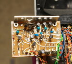
You are correct, it is a german Uher Monitor recorder, attached is a picture of the motor controller, there was only one Electolyte, I had already replaced it with no difference , all others are tantalum caps. I will connect cap as you describe. thanks

- - - Updated - - -

From the style of schematic it looks like a Grundig or Telefunken machine. You can do a crude check for a high impedance suply by temporarily connecting a capacitor of ~100uF across points 302 and 303 (negative side to 302). If it makes a difference to the hum level it is probably the power supply at fault. I doubt the power supply uses tantalum capcitors, they would normally be wet electrolytics and they do deteriorate with time.

Brian.

Hi again, just want to double check, 302 is + supply and 303 is ground, shouldn't the ground be at at 303 ?
Thanks

- - - Updated - - -

From the style of schematic it looks like a Grundig or Telefunken machine. You can do a crude check for a high impedance suply by temporarily connecting a capacitor of ~100uF across points 302 and 303 (negative side to 302). If it makes a difference to the hum level it is probably the power supply at fault. I doubt the power supply uses tantalum capcitors, they would normally be wet electrolytics and they do deteriorate with time.

Brian.

Forgot to mention that I have recapped the electrolytes on the power supply of the machine (2200uf,etc...) without any difference
 

Attachments

  • DSC03088.JPG
    DSC03088.JPG
    719.7 KB · Views: 99

My apologies, its difficult to read on a small screen!

303 is ground, the positive supply is on 302.

Basically thee are three routes the hum can travel, through the ground, through the supply or by radiation into nearby wiring. The ground and supply are the most likely cause because they directly connect to the audio circuits but unless you have changed the wires they should be as Uher designed them. I doubt the tantalum capacitor are the problem but it is worth checking the waveforms at the collectors of T2, T4 and T6, particularly the width of the pulses which should be equal. If there is a difference it would result in the motor current being unstable, even if it appears to be running normally. The 51Hz you mentioned may be ripple from only one phase of the motor, it's difficult to tell whether there are three pulses per revolution, each at 51Hz or whether it is the frequency of one complete revolution.

Brian.
 
  • Like
Reactions: hafrse

    hafrse

    Points: 2
    Helpful Answer Positive Rating
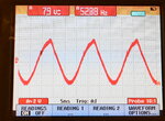
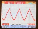
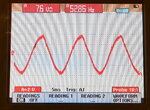
Here are the traces on the collector of T6.jpg, T4.jpg and T2.jpg
 

Attachments

  • t2.JPG
    t2.JPG
    1.3 MB · Views: 96
  • t4.JPG
    t4.JPG
    1.7 MB · Views: 90
  • T6.JPG
    T6.JPG
    1.3 MB · Views: 100

Those don't look right but to be certain you need to refer to the service manual.

This is what I would try:
1. Take note of the positions of R17 and R18 in case you have to turn them back again.
2. Ideally using a dual trace oscilloscope, adjust R18 until the waveforms at the collector of T4 and T6 are the same amplitude. One will increase while the other decreases as you turn R18. Note that they will be out of phase but it is only the amplitude you need worry about at the moment. Take note of the amplitude.
3. Measure the waveform at the collector of T2 and adjust R17 so it matches the other two transistors.

That should ensure all three phases are equal so one isn't taking more current than the others. If the problem is an imbalance it should fix it.

Brian.
 

Status
Not open for further replies.

Part and Inventory Search

Welcome to EDABoard.com

Sponsor

Back
Top