Continue to Site

Welcome to EDAboard.com

Welcome to our site! EDAboard.com is an international Electronics Discussion Forum focused on EDA software, circuits, schematics, books, theory, papers, asic, pld, 8051, DSP, Network, RF, Analog Design, PCB, Service Manuals... and a whole lot more! To participate you need to register. Registration is free. Click here to register now.

Audio Amplifier cuircit by LM386 and LM358

Status
Not open for further replies.

mf1364

Full Member level 3
Full Member level 3
Joined
Dec 4, 2007
Messages
185
Helped
2
Reputation
4
Reaction score
2
Trophy points
1,298
Activity points
2,700
Hi every body
I want to design an audio amplifier circuit using LM386 and LM358 . after that I decide to use it in a intercom circuit so does any body have a industrial and practical circuit for me and I have tried The advised circuit in the data sheet but it doesn't work good ! by the way I am looking forwards to finding a preamplifier circuit by transistor for Amplifying Mic Signal please suggest schematic for this one too . ps = 5v or 12V
 

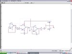
you can use this circuit: Amplifier.JPG
your in put is left v+.
and your out put is RL that if you want current upper than 80ma you should use a complementary amplifier As rl and put your RL at out put of complementary amplifier. Voltage gain of this circuit is calculated :650 with this circuit you can obtain (my circuit with complementary) 28 watts with the 4 ohm load.(actual watt) if you decrease ohm of your load power will increase!
 
**broken link removed**

:wink:
thanks for the link , I try this circuit but it doesn't work . I use basic audio amplifier but unfortunately it didn't work and I used 12V instead 9V and for some of the Electrolyte capacitors I used the same capacity and higher voltage for example 470uf-50v instead of 470uf-16v or 10uf - 35v instead 10uf - 16v . do you think can it cause circuit don't work ?
 

Hi
Yes i using this circuit. its work is well
good , you know I am testing IanP circuit right now , after that I will test your advised circuit , can you explain about your circuit ? for example what does each component exactly do ?
 

hey Gentleman!
Hi
The act of U3a(first opamp) is buffering (its input impedance is very high) . with this stage all of your input sources are match with this amplifier.C2 is Coupling capacitor.Ua4(second opamp) is a inverting amplifier with gain:Av=-R3/R4.that R4 is input impedance of this stage. because the out put impedance of each op amp is very low , this op amp is matched with preceding opamp.
The performance of Ua5 is identical with ua4. The total out put gain will be -(68/1)*-(10/1)=+680. if you want high current at out put you should add a complementary buffer at out put. the quality of this circuit is very high and its THD is low and its efficiency is good.
Best Wishes
Goldsmith
 

if you want high current at out put you should add a complementary buffer at out put. the quality of this circuit is very high and its THD is low and its efficiency is good.
Saying this about an LM358 audio preamplifier is somewhat ignorant in my opinion, although the crossover distortions of the LM358 class-B output stage can hardly be missed hearing. But you still make the amplifier quality worse, by adding a complementary buffer...

P.S.: The lab circuit linked by Ianp also uses a LM358, but overcomes the crossover distortion problem by forcing the OP to class A operation, with pull-down resistor R5. Unfortunately, the second (tone control) stage misses a similar means.
 
Last edited:

Dear FvM
Hi
Thank you for your answer.
but you should know that All of the op amps are biased in class AB region. for example Lm358 is in class AB too. i used it in some of my projects. and i need to ask a important question from you: why you dont want to test my circuit? the response of it Will magic for you. if your supply did not have a good ripple rejection ratio , you will have problem with amplifier circuits.
this circuit is my driver for my Class D amplifier. i used it as class AB amplifier driver and class D amplifier driver.
so In fact this circuit has not problem. and i saw the suggested circuit , that was good too.
Thank you for your attention.
All the best
Goldsmith
 

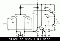
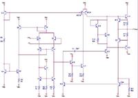
The LM358 is clearly class B, as the internal circuit shows. The driver stage node (Q12.C) needs to swing three diode voltage drops to switch from current source to sink. The 50 µA current source creates class A operation only for very light loads.

 
Dear FvM
Hi
Please see this page that is a one page of the datasheet of lm358 that i got it from motorola incorporation:lm358.JPG
It is biased as class AB as well as.
Kind Regards
Goldsmith
 

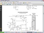
Your circuit is identical to the (original) National schematic, but showing the transistor level circuits of the current sources. However, it's neither class AB in my view. A class AB output stage would have NPN and PNP output transistors biased to active state simultaneously. A bias voltage source as in UA741 is required to achieve this, see Q19/Q18 in the below schematic.

 
Dear friend
Hi
Your circuit is not datasheet of lm358. because the out put supplied just with one transistor(in actual ). but your out put is from
Q14 And q20(complementary) . see my circuit . its out put is from emitter of q12 that not connected to the emitters of q13 and q11. see my attachment please! i got it from the Motorola. but i dont know that your circuit is from where?
say to me , that why you don't want to test it , please??!!!! i said that this circuit working know as well as( i have it in my home). if you want, i can send to you , video of its work!!!!!!!!!!!!!
Sincerely
Goldsmith

---------- Post added at 21:58 ---------- Previous post was at 21:50 ----------

I suggest you , downloading the full data sheet of lm358.
in your circuit i cant see jfet in current source but there is Jfet in datasheet.. your circuit is for which Ic?
 

Your circuit is not datasheet of lm358.
No. Post #14 brings a UA741 transistor level circuit, as said, and shown as an example of a class AB output stage. LM358 circuit is in post #12.

I experienced the effects of LM358 crossover distortions many years ago and don't need additional empirical evidence for it. I'm still using this part in many designs where it's appropriate, but not for audio related applications.
 

Dear friend , i think your Ic was Defect. because all of my pre amplifiers are with Lm 358(it has 2 opamp in one package.
Ok , i suggest you , simulation with Pspice software.
If you want , i can take photo from face of my oscilloscope that showed its out put without crossover distortion!!
 

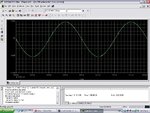
Can you see crossover distortion??????!!!!!
My in put that you can see is 5 mv . and my voltage gain is -2 and my out put wave form is 10mv with 180 degree phase shift.

---------- Post added at 22:27 ---------- Previous post was at 22:26 ----------

So you can Believe that LM358 is in class AB region.
 

Can you see crossover distortion?
Not in this simulation, you need to slightly increase the output voltage to make the output current exceed the 50 µA current source bias.
So you can Believe that LM358 is in class AB region.
It's not a matter of believe rather than analyzing the circuit. It's still class A, falling into class B above 50 uA.

P.S.: I didn't consider an important point. The usual LM358 macro model doesn't represent the output stage correctly. See this comment in the model file.
Output crossover distortion with dual supplies is not modeled.
 
Last edited:
  • Like
Reactions: LvW

    LvW

    Points: 2
    Helpful Answer Positive Rating
Status
Not open for further replies.

Similar threads

Part and Inventory Search

Welcome to EDABoard.com

Sponsor

Back
Top