Vermes
Advanced Member level 4


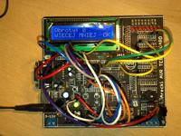
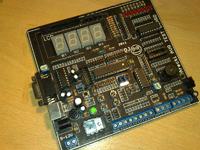
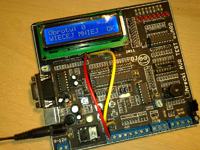
This project was based on ZL2-AVR kit from BTC.
Features:
- display HD44780
- 4x 7-segments display
- 8x LED
- RS232
- I2C
- matrix keyboard 2x2
- PS2 keyboard
- buffers
- potentiometer
- TSOP IR receiver
- sockets for 1wire and 6 sockets for external interfaces
- DIP14 and DIP16 bases
Design:
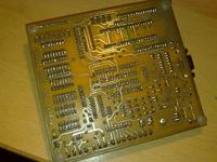
Schematic diagram was made in EAGLE on base of ZL2-AVR scheme. As you can not place all the peripherals in such a system on one layer, the board was designed as double sided with emphasis on the bottom layer.
Implementation:
The board was made in thermal transfer method with sequentional etching. Remember that the holes of both layers must match perfectly. The description layer is self-adhesive with a laser print.
Assembly:
Guides were made with a thin wire. Make sure that all the guides were made, then stick a foil with a description and make holes for the elements using a needle. The rest of the assembly proceeds normally.
Elements used:
- LCD display 2x16 characters
- AVR microcontroller, DIP28
- 4x 7-segments green displays 0,28 common cathode
- 3x HEADER 1x40
- socket for HEADER 1x40
- 2x HEADER 2x40
- female angle socket DB9 for print
- KF301 connector 3pin (-)
- 7x KF301 connector 2pin (-)
- 5V stabilizer, TO-220
- 28pin precision stand
- 16pin normal stand
- 14pin normal stand
- ceramic capacitor 100nF/50V r5.08
- electrolytic capacitor 0.1uF/50V 5x11 105C
- IR receiver 36 kHz
- etching: sodium persulfate 100g
- 9x 3mm diffusion red LED
- 3x resistor 220R 5% 0,25W
- rectifier bridge 1,5A/1000V
- chip: Interface RS232
- chip expander for line I2C
- DC socket dia 5,5x2,5mm for print, plastic
- ps/2 socket for print
- Tact Switch 6x6mm, h=8,0mm
- lying assembly potentiometer 10k
- quartz 8,00MHz – HC49U
- IDC connector 10pin


Link to original thread (useful attachment) – Płytka Testowa ATMEGA 8 replika ZL2AVR
Last edited: