Vermes
Advanced Member level 4

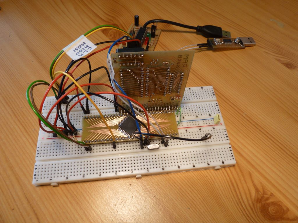
When creating projects with microcontrollers, usually testboards are used, but they are not cheap. This thread presents how to create a cheap teastboard where all the expensive elements like chips, RAM, RTC can be used again without any damage to them. All rest elements are SMD type.
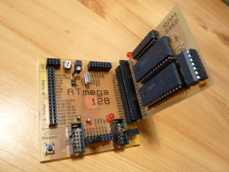
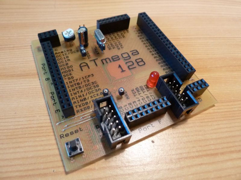
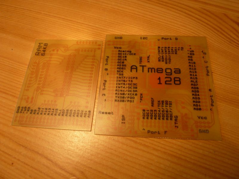
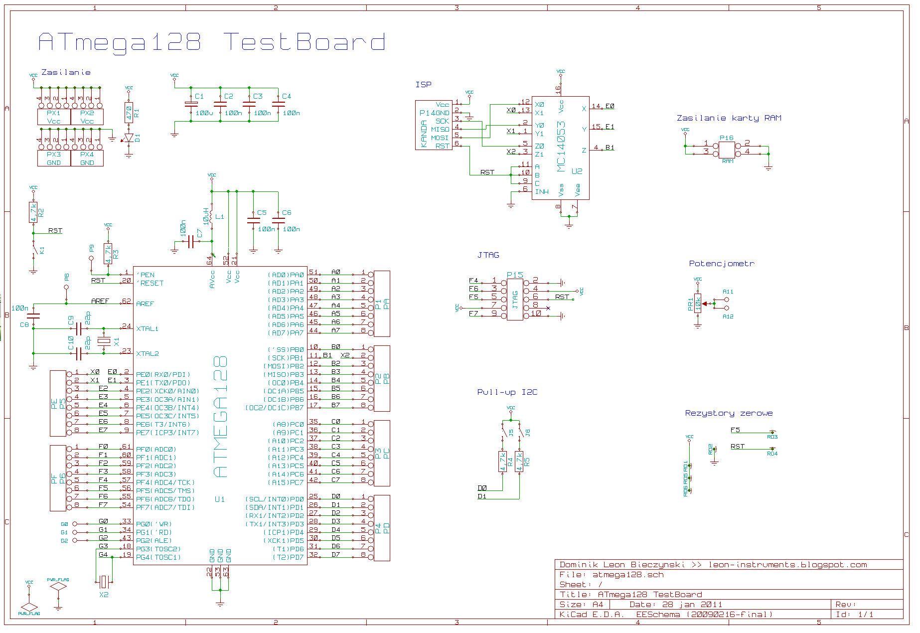
ATmega128 TestBoard
The board is equipped with an ISP connector and a JTAG with IDC-10. Besides that, it has a small potentiometer used to ADC or to adjust the LCD contrast. The power connectors are placed in two corners. They can supply other modules or displays.
Attention! Do not connect in the same time two power supplies like ISP programmer and standard power supply. It's because of no build-in stabilizer.
The power on is signalized by a red LED. The board is also equipped in two resistor 4,7k used to pull-up I2C. Just need to use a jumper near D socket.
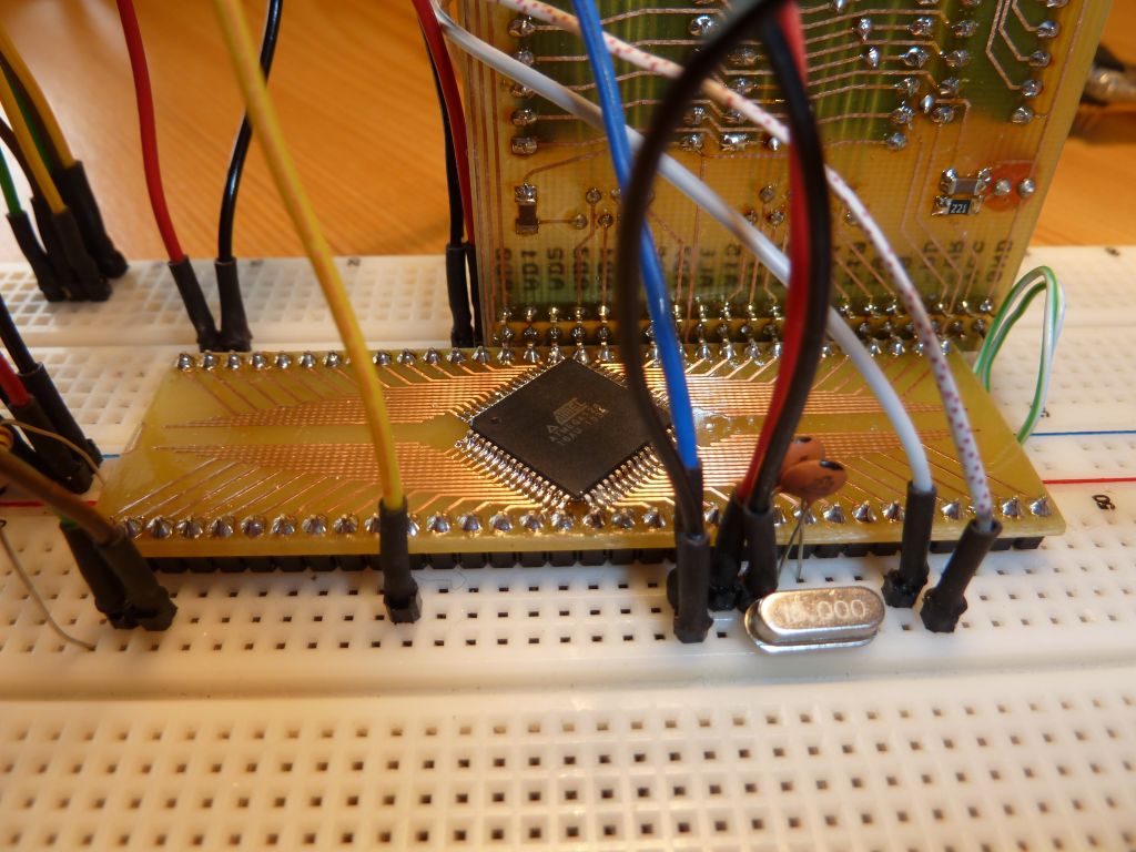
The XTAL socket is used for connecting the CPU clocking quartz.
The TOSC is a place for 32kHz quartz to the internal RTC (real time clock). If no RTC is used, this socket can be used like a simple G socket output.
 **broken link removed**
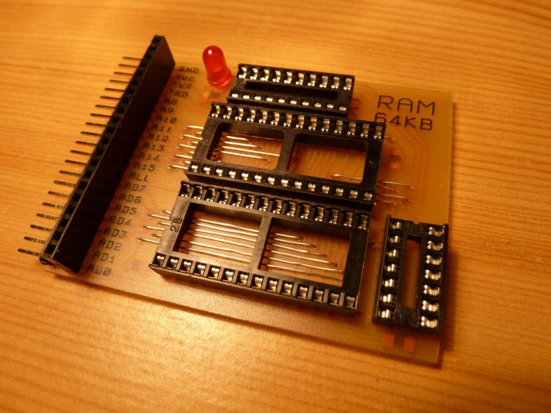
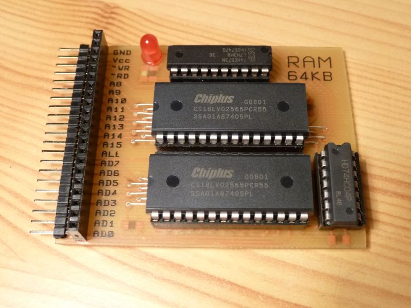
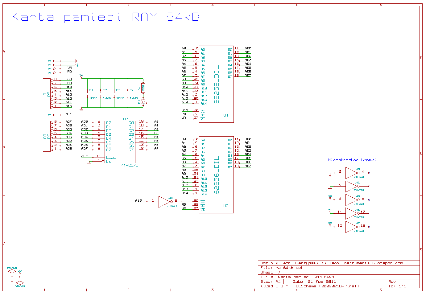
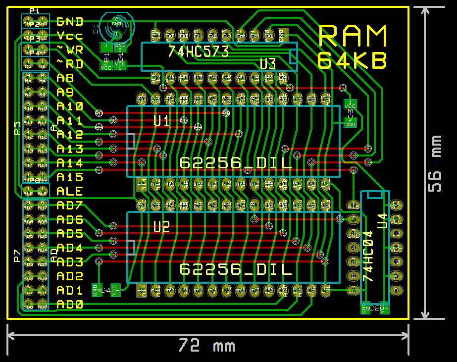
RAM 64k
Atmega128 enables working with RAM (SRAM) at maximum size of 64kB without paging.
The module uses two 62256 chips. These are RAMs of size 32kB. Why not one 62512? Because it's harder to buy. 7407 and 74573 must be in HC version – 74HC04 and 74HC573
Atmega128 has 4kB of internal RAM. But after connection 64 there will not be 68 because of 16-bit long address bus.
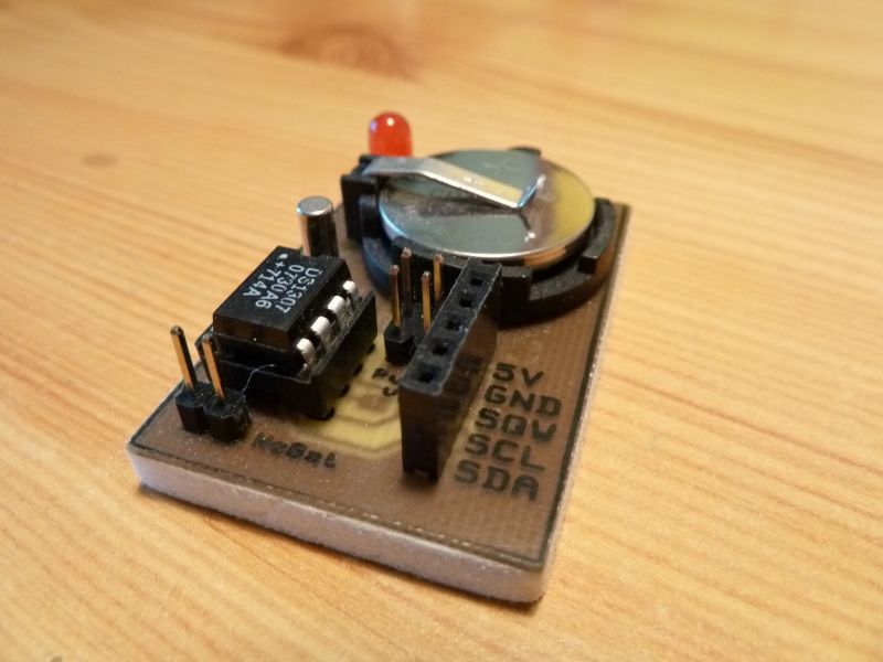
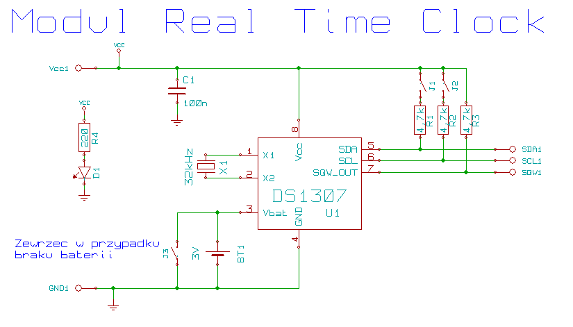
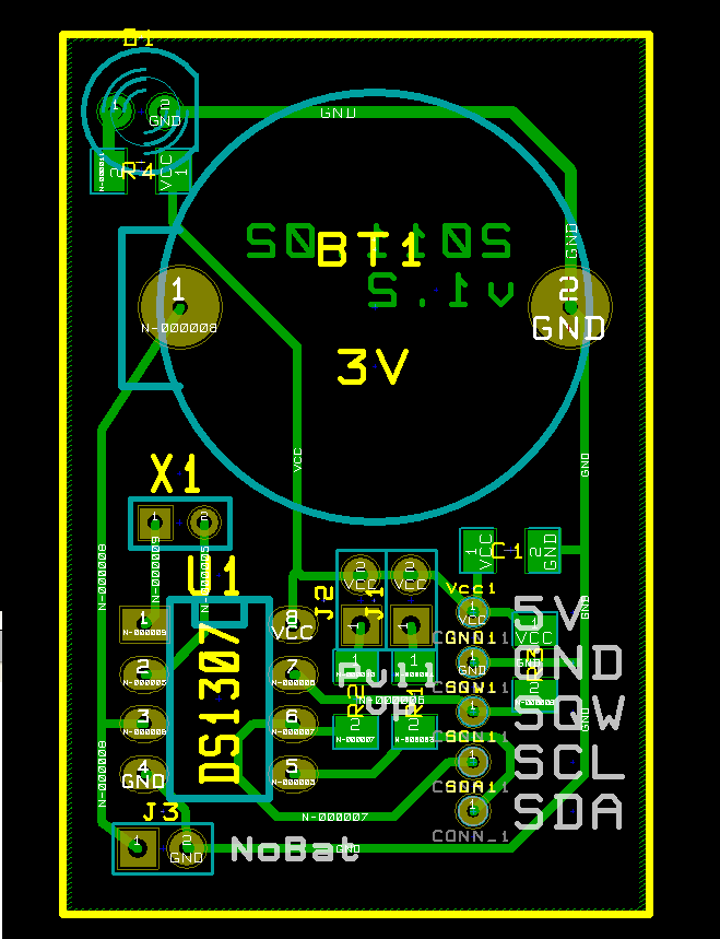
Real time clock DS1307
The DS1307 is RTC with its own oscillator and battery supply. The communication is by I2C. The board has 4,7k resistors which can be connected using jumpers. The board can work without a battery – a jumper on NOBAT is needed.
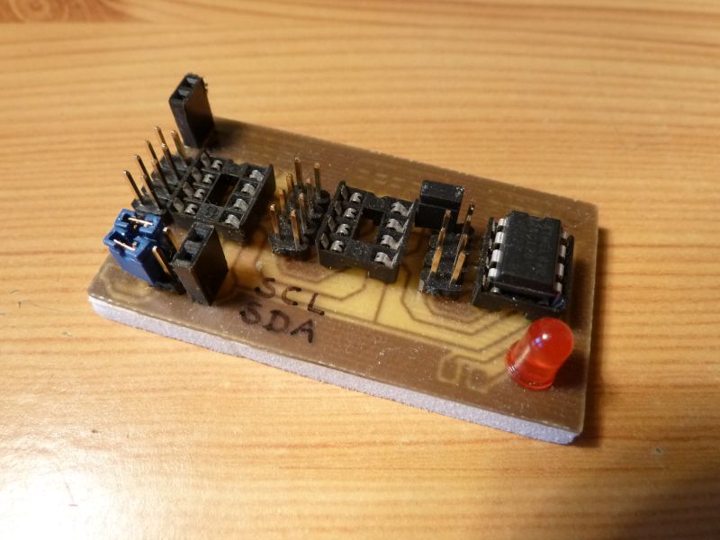
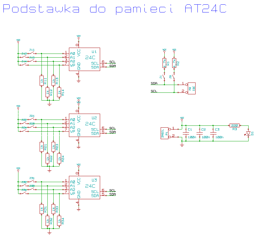
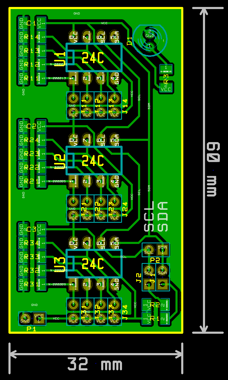
EEPROM 24C memory
It's a holder for three 24 Cxxx (xxx – size in kB) memory chips. The communication is also by I2C. Jumpers must be used to change the addresses of memory chips. Example:
AT24C128 without any jumper has an address of 160 for writing and 161 for reading. More information can be found in the memory documentation. The memory can be protected against writing. There is also a possibility to connect 4,7k resistors as a pull-up on SDA and SCL lines.
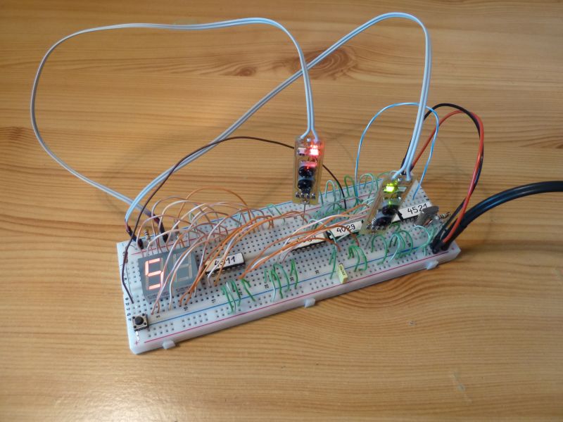
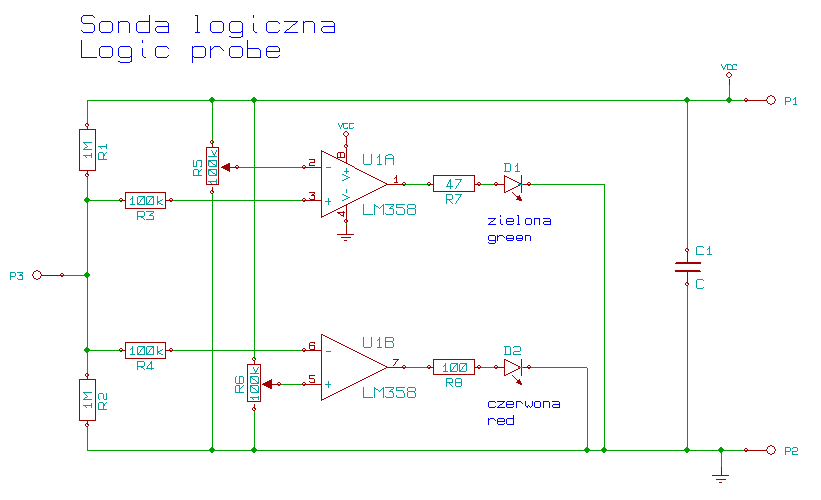
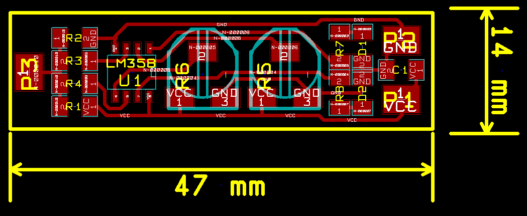
Logical probe
The logical probe is a basic-electronics equipment. The green LED is logical 1, the red LED logical 0 and there are no LEDs of high impedance or no connection.
The two potentiometers are used to adjust tense thresholds. Before the first usage the potentiometers should be set to glow the green LED above 3,5V, and the red one below 1,5V.
The purpose of using this two potentiometers is to test other systems than CMOS.

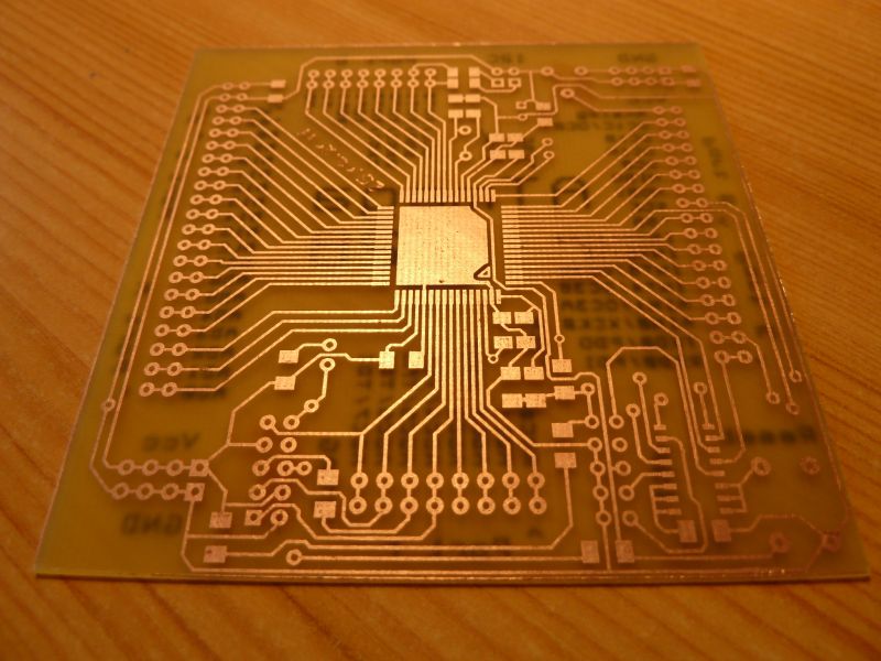
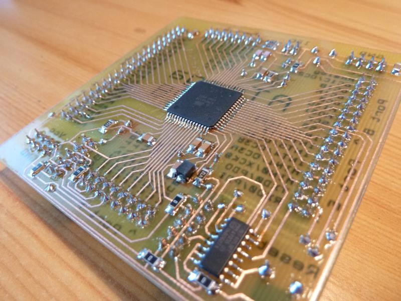
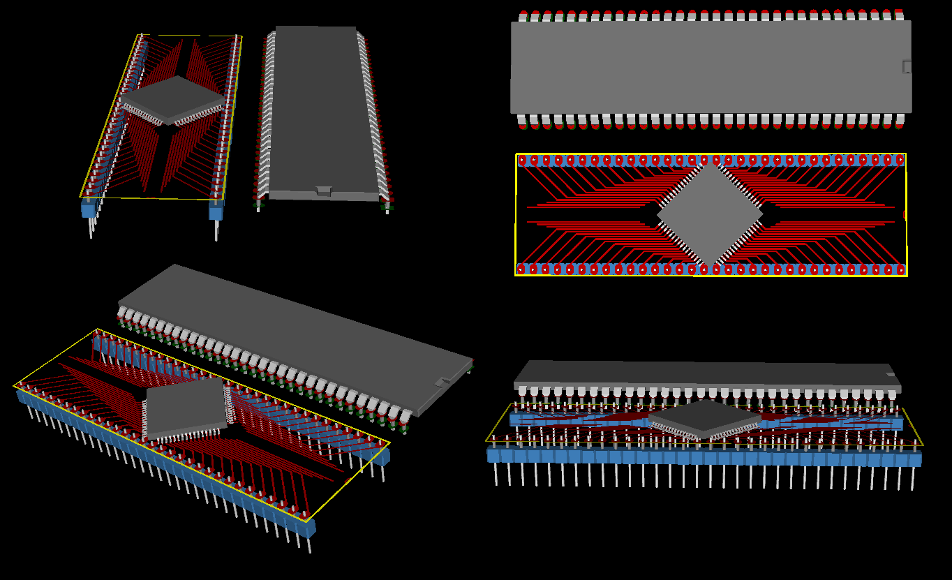
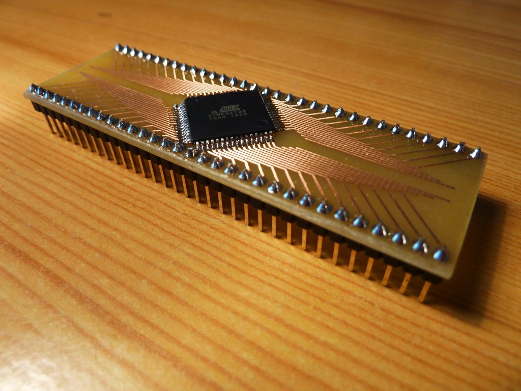
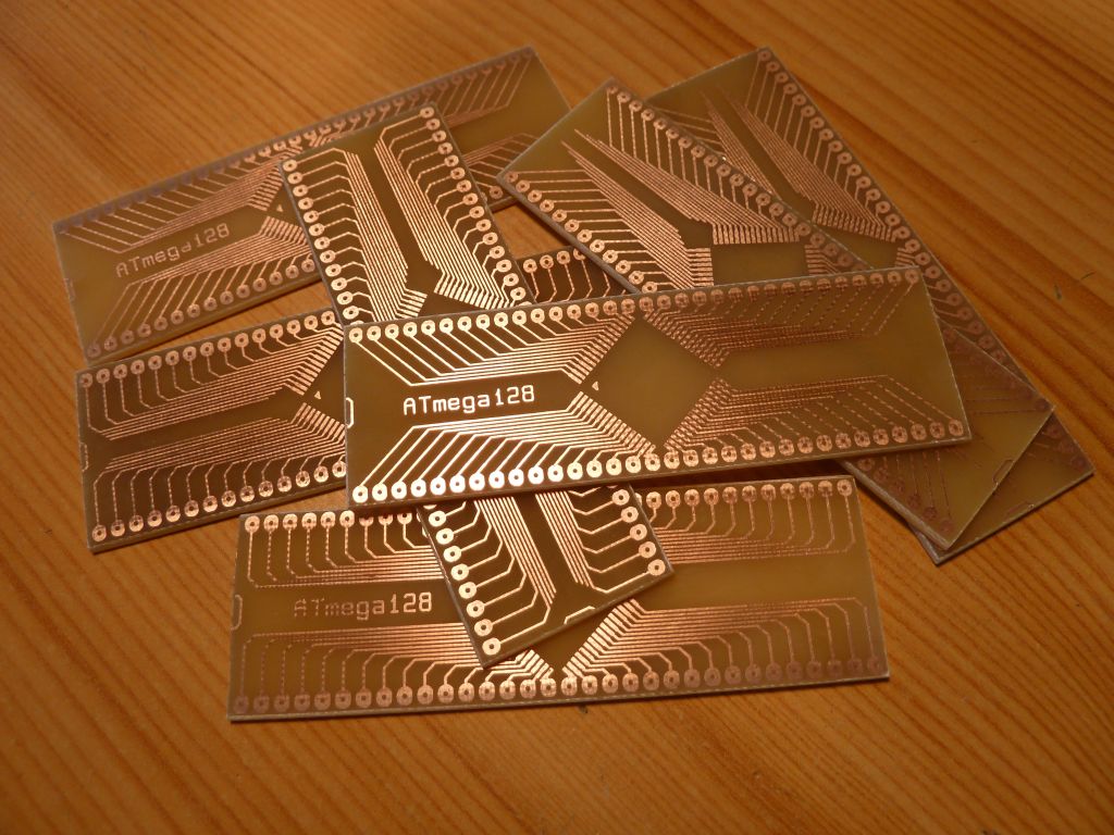
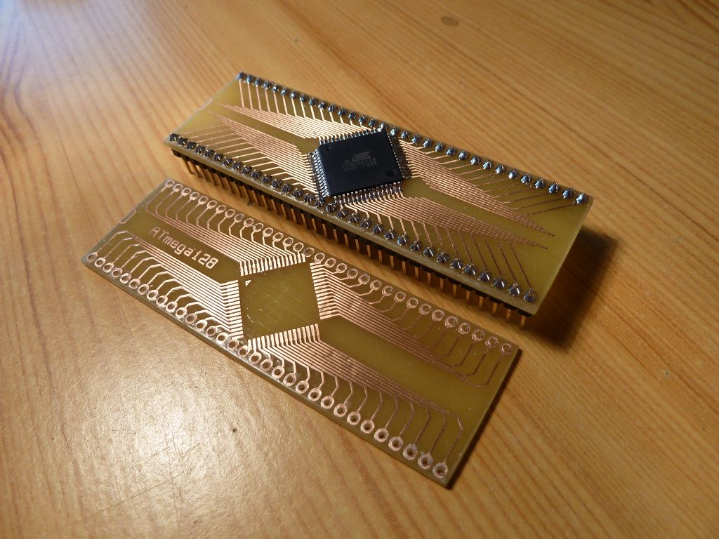
ATmega128 DIL64
Atmega128 is produced only in SMD therefore an DIL64 housing was constructed. To build this, a 1,5mm lamina must be used.
Link to the original thread where some code and useful attachments can be found - ATmega128 TestBoard