Continue to Site

Welcome to EDAboard.com

Welcome to our site! EDAboard.com is an international Electronics Discussion Forum focused on EDA software, circuits, schematics, books, theory, papers, asic, pld, 8051, DSP, Network, RF, Analog Design, PCB, Service Manuals... and a whole lot more! To participate you need to register. Registration is free. Click here to register now.

Asus AC Adaptor (Output: 19V) - Model AD890026 stopped working after drop

Status
Not open for further replies.

brunoaduarte

Newbie level 6
Newbie level 6
Joined
Oct 13, 2008
Messages
11
Helped
0
Reputation
0
Reaction score
0
Trophy points
1,281
Activity points
1,354
Hi!

My Asus AC Adaptor (Input: 100-240V / Output: 19V) - Model AD890026 that stopped working after a drop.

- I've checked the fuse and it's ok.
- Made a visual inspection and all the solder seems fine.
- Removed and tested the yellow MPX40 part with a multimeter and it measures 283.7 nF
- The big 47 uF / 400V capacitor charges with ~190V when i connect it to the wall plug.
- No 19V output on the PCB.

Can someone help me finding the problem with it ? Where should i start looking and/or which tests could i make here ?

I've attached some pictures (including a ZIP file with the high res images).

Thanks!
 

Attachments

  • IMG_0157.JPG
    IMG_0157.JPG
    377.2 KB · Views: 241
  • IMG_0206.JPG
    IMG_0206.JPG
    296.4 KB · Views: 209
  • IMG_0207.JPG
    IMG_0207.JPG
    186.7 KB · Views: 213
  • IMG_0208.JPG
    IMG_0208.JPG
    179 KB · Views: 200
  • IMG_0209.JPG
    IMG_0209.JPG
    155.5 KB · Views: 206
  • IMG_0210.JPG
    IMG_0210.JPG
    210.9 KB · Views: 215
  • IMG_0211.JPG
    IMG_0211.JPG
    254 KB · Views: 211
  • IMG_0212.JPG
    IMG_0212.JPG
    238.1 KB · Views: 224
  • IMG_0213.JPG
    IMG_0213.JPG
    237.7 KB · Views: 241
  • IMG_0216.JPG
    IMG_0216.JPG
    226.3 KB · Views: 309
  • asus_AD890026.zip
    15.5 MB · Views: 204

Hello brunoaduarte,
You need to remove the white glue from the solder side of the PCB so you
can see what's underneath it all.
Also, you need to check for cracks on the PCB tracks, especially around
the chopper transformer and switching MOSFET. The one connected to the
heatsink.
If you have a magnifying glass or an inspection lamp, use that to look for
any cracks, as there may even be micro-fractures.
Check very closely at the SMD components for fractures also. You can do
rough checks on your multimeter to ensure none of them are broken.
Check your 19V output lead for any wire breaks within it. A low ohms
continuity check would be best. (This is an unlikely problem, but would be
good to check regardless).
Please let us know how you get on... Good luck!!!
Regards,
Relayer

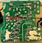
EDIT: It seems I didn't check the solder side of your
PCB close enough. Have a look at your revised picture, and you should see a
cracked solder joint. This may be the real culprit.

Solder Side.jpg

P.S. I have to say it, but it just shows how poorly the Chinese make devices
for themselves or contracts for other companies. How good is the toroidal
coil wound? It looks like a 5 year old wound it. :???:
 
Last edited:
Hello brunoaduarte,
You need to remove the white glue from the solder side of the PCB so you
can see what's underneath it all.
Also, you need to check for cracks on the PCB tracks, especially around
the chopper transformer and switching MOSFET. The one connected to the
heatsink.
If you have a magnifying glass or an inspection lamp, use that to look for
any cracks, as there may even be micro-fractures.
Check very closely at the SMD components for fractures also. You can do
rough checks on your multimeter to ensure none of them are broken.
Check your 19V output lead for any wire breaks within it. A low ohms
continuity check would be best. (This is an unlikely problem, but would be
good to check regardless).
Please let us know how you get on... Good luck!!!
Regards,
Relayer

EDIT: It seems I didn't check the solder side of your
PCB close enough. Have a look at your revised picture, and you should see a
cracked solder joint. This may be the real culprit.

View attachment 141796

P.S. I have to say it, but it just shows how poorly the Chinese make devices
for themselves or contracts for other companies. How good is the toroidal
coil wound? It looks like a 5 year old wound it. :???:

Hi @Relayer, thanks for the reply!

I've inspected all the pcb with a magnifying glass couple of times, there seems to be no issue at all with the pcb.

The solder point you marked is not broken, it's just a lack of solder on the right side of the pin, the left side is totally soldered (anyway i fixed this solder now).

I've checked the output of the KBP20 bridge rectifier and it outputs 180V DC, so it seems circuit is fine till there, not sure on how to check the rest of it.
 

There is a good possibility of some cracked SMT resistors in a critical part of the circuitry after such a fall. You can also get cracked capacitors, but that may not neccasary prevent it from starting up. It may influence the way it performs (response, stability etc.). You should inspect the SMT resistors under a microscope for any signs of cracks and verify by measurement. They are not easy to spot without some help.
 
Status
Not open for further replies.

Part and Inventory Search

Welcome to EDABoard.com

Sponsor

Back
Top