Continue to Site

Welcome to EDAboard.com

Welcome to our site! EDAboard.com is an international Electronics Discussion Forum focused on EDA software, circuits, schematics, books, theory, papers, asic, pld, 8051, DSP, Network, RF, Analog Design, PCB, Service Manuals... and a whole lot more! To participate you need to register. Registration is free. Click here to register now.

ARM LPC2148 KIT isprogrammed using flash tool but controllers not working

Status
Not open for further replies.

chamanlatapankaj

Newbie level 5
Newbie level 5
Joined
Jul 25, 2015
Messages
9
Helped
0
Reputation
0
Reaction score
0
Trophy points
1
Visit site
Activity points
66
i am working on ARM LPC2148 KIT .The kit is isprogrammed by using flash tool correctly but there is no change on PINS Signal,but the program written is properly working in Proteus.
Thanks in Advance
 

Welcome to the real world.

There are often significant differences between running code in a simulator and running the same code on physical hardware, particularly the more elaborate the simulator.

Please post your code using the CODE or SYNTAX tags, so that we can examine it.

Proper configuration of the system clock/PLL is often an issue, which Proteus seems to typically overlook.

BigDog


Code C - [expand]
1
2
3
4
5
6
7
8
9
10
11
12
13
14
15
16
17
18
19
20
21
22
23
#include<LPC214x.h> // Define LPC2148 Header File 
#define led IOPIN1 // Define LED to Port1 
#define tled IO1DIR // Define Port1 as output 
void delay(int x); 
int main() 
    {
        PINSEL1= 0x00000000; // Define port lines as GPIO 
        tled = 0x00FF0000; // Define P1.16 – P1.23 as O/P 
        led = 0x00000000; // Define P1.16 – P1.23 as zero 
        while(1) // Loop forever 
            { 
                led = 0x00FF0000; // Turn ON P1.16 – P1.23 
                delay(20000); 
                led = 0x00000000; // Turn OFF P1.16 – P1.23 
                delay(2000); 
    } 
    } 
    void delay(int x) 
        { 
            unsigned int k,l; 
            for(k = x;k > 0;k--) 
            for(l = 0;l < x;l++);
        }

 
Last edited by a moderator:


Code C - [expand]
1
2
3
4
5
6
7
8
9
10
11
12
13
14
15
16
17
18
19
20
21
22
23
#include<LPC214x.h> // Define LPC2148 Header File 
#define led IOPIN1 // Define LED to Port1 
#define tled IO1DIR // Define Port1 as output 
void delay(int x); 
int main() 
    {
        PINSEL1= 0x00000000; // Define port lines as GPIO 
        tled = 0x00FF0000; // Define P1.16 – P1.23 as O/P 
        led = 0x00000000; // Define P1.16 – P1.23 as zero 
        while(1) // Loop forever 
            { 
                led = 0x00FF0000; // Turn ON P1.16 – P1.23 
                delay(20000); 
                led = 0x00000000; // Turn OFF P1.16 – P1.23 
                delay(2000); 
    } 
    } 
    void delay(int x) 
        { 
            unsigned int k,l; 
            for(k = x;k > 0;k--) 
            for(l = 0;l < x;l++);
        }


Please help me why this programis not running on arm lpc2148 kit.
 

Code:
#include<LPC214x.h> // Define LPC2148 Header File 
 
#define led IOPIN0 // Define LED to Port1
#define tled IO1DIR // Define Port1 as output

void delay(unsigned int x);
  void initialise(void)
         {
              
                PLL0CFG &= 0xE0;    // Reset MSEL0:4
                PLL0CFG |= 0x04;    // MSEL(PLL Multiply) = 3
                PLL0CFG &= 0x9F;    // Reset PSEL0:1
                PLL0CFG |= 0x20;    // PSEL(PLL Devide) = 2
                PLL0CON &= 0xFC;    // Reset PLLC,PLLE
                PLL0CON |= 0x01;    // PLLE = 1 = Enable PLL

                PLL0FEED = 0xAA;    // Start Update PLL Config
                PLL0FEED = 0x55;
                while (!(PLL0STAT & 0x00000400));  // Wait PLL Lock bit
                PLL0CON |= 0x02;    // PLLC = 1 (Connect PLL Clock)
                PLL0FEED = 0xAA;     // Start Update PLL Config
                PLL0FEED = 0x55;
                VPBDIV &= 0xFC;    // Reset VPBDIV
                VPBDIV |= 0x01;    // VPB Clock(pclk) = cclk / 1
                // End of Initial PLL for Generate Processor Clock

                // Start of Initial MAM Function
                MAMCR = 0x00;     // Disable MAM Function
                MAMTIM = 0x03;     // MAM Timing = 3 Cycle of cclk
                MAMCR = 0x02;     // Enable MAM = Full Function
              
         }

int main() 
	{ 
	

		PINSEL2 = 0x00000000; // Define port lines as GPIO 
		tled = 0x00FF0000; // Define P1.16 – P1.23 as O/P 
		led = 0x00000000; // Define P1.16 – P1.23 as zero 
	initialise();
		while(1) // Loop forever
			{ 
					led = 0x00ff0000; // Turn ON P1.16 – P1.23 
				
	} 
	} 
	void delay(unsigned int x) 
{ 
	unsigned int k,l; 
for(k = 0;k<x;k++)
	{
for(l = 0;l <8002;l++);
	}
}

check this program with the clock and PLL SETTING but there is no change on controller pins status.
 
Last edited by a moderator:

Can you upload the schematics of your development board? Or post a URL to its website?

When properly configuring the PLL, the crystal frequency must be considered.

Also, it appears you are using KEIL MDK-ARM is this correct?

Certainly one issue is the macro #defines highlighted in RED, you are defining the identifier led as IOPIN0, Port 0, however you then define the identifier tled as IO1DIR, Port 1 Direction.

Code:
#include<LPC214x.h> // Define LPC2148 Header File 
 
[COLOR="#FF0000"]#define led IOPIN0[/COLOR] // Define LED to Port1
[COLOR="#FF0000"]#define tled IO1DIR[/COLOR] // Define Port1 as output

...
...

int main() 
{ 
	

	PINSEL2 = 0x00000000; // Define port lines as GPIO 
	tled = 0x00FF0000; // Define P1.16 – P1.23 as O/P 
	led = 0x00000000; // Define P1.16 – P1.23 as zero 
	initialise();

	while(1) // Loop forever
	{ 
		led = 0x00ff0000; // Turn ON P1.16 – P1.23 
				
	} 
}

Instead of:

Code:
#define led IOPIN0 // Define LED to Port1
#define tled IO1DIR // Define Port1 as output

Try:
Code:
#define led IOPIN0 // Define LED to Port0
#define tled IODIR0 // Define Port0 as output


BigDog
 

Code:
#include<LPC214x.h> // Define LPC2148 Header File 
 
#define led IOPIN1 // Define LED to Port1
#define tled IO1DIR // Define Port1 as output

void delay(unsigned int x);
  void initialise(void)
         {
              
                PLL0CFG &= 0xE0;    // Reset MSEL0:4
                PLL0CFG |= 0x04;    // MSEL(PLL Multiply) = 3
                PLL0CFG &= 0x9F;    // Reset PSEL0:1
                PLL0CFG |= 0x20;    // PSEL(PLL Devide) = 2
                PLL0CON &= 0xFC;    // Reset PLLC,PLLE
                PLL0CON |= 0x01;    // PLLE = 1 = Enable PLL

                PLL0FEED = 0xAA;    // Start Update PLL Config
                PLL0FEED = 0x55;
                while (!(PLL0STAT & 0x00000400));  // Wait PLL Lock bit
                PLL0CON |= 0x02;    // PLLC = 1 (Connect PLL Clock)
                PLL0FEED = 0xAA;     // Start Update PLL Config
                PLL0FEED = 0x55;
                VPBDIV &= 0xFC;    // Reset VPBDIV
                VPBDIV |= 0x01;    // VPB Clock(pclk) = cclk / 1
                // End of Initial PLL for Generate Processor Clock

                // Start of Initial MAM Function
                MAMCR = 0x00;     // Disable MAM Function
                MAMTIM = 0x03;     // MAM Timing = 3 Cycle of cclk
                MAMCR = 0x02;     // Enable MAM = Full Function
              
         }

int main() 
	{ 
	

		PINSEL2 = 0x00000000; // Define port lines as GPIO 
		tled = 0x00FF0000; // Define P1.16 – P1.23 as O/P 
		led = 0x00000000; // Define P1.16 – P1.23 as zero 
	initialise();
		while(1) // Loop forever
			{ 
					led = 0x00ff0000; // Turn ON P1.16 – P1.23 
				
	} 
	} 
	void delay(unsigned int x) 
{ 
	unsigned int k,l; 
for(k = 0;k<x;k++)
	{
for(l = 0;l <8002;l++);
	}
}

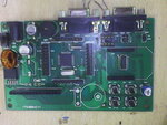
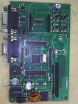
yes i am using MDK KEIL ARM.This is the code right now i m testing on kit. i am sending you the images ofmy development board. IMG_20150728_144538.jpgIMG_20150728_144502.jpg
 
Last edited by a moderator:


i dont have the schematic for this development board.i checked this develpoment board on internet but this type of develpoment board is now not available.can you send me any program of led blinking working on another armLPC2148 kit.i will take care of the rest if the program works on this development board.
 

this is the link of my development board i found.if this can help then let me know.there is no other detail i found on the internet.
**broken link removed**.
 

this is the link of my development board i found.if this can help then let me know.there is no other detail i found on the internet.

For future reference, a development board without a schematic is essentially worthless, I would suggest you contact them and request they provide a schematic.

You still have failed to mention the external crystal or oscillator frequency driving the system clock, you need to know at least the base frequency to properly calculate the PLL settings.
The crystal frequency, silver narrow can besides the microcontroller, is unreadable in both your and the vendors images.

As you are using the KEIL MDK-ARM Compiler, they provide several example "Blinky" applications in either the Examples or Boards directory/folders, just look for an example which is written for the LPC2148 or another LPC21xx related version of the microcontroller.

Look in the Boards/KEIL directory for "Blinky" examples in any of the MCB21xx series of dev boards, as the differences between the LPC21xx series of microcontrollers is primarily the peripheral modules.

I've attached a variation of the code you previously posted which blinks the LEDs in simulation, I do not currently have an LPC2148 based dev board to test it on hardware.

BigDog
 

Attachments

  • chamanlatapankaj.zip
    63.8 KB · Views: 140

hi sir,
here i am sending you the images of my new arm kit and its sechematic.i am not able to burn the program in this.i always get the error autobaud fail.usb cable is correct.i am using flashmagic tool and compiler is keil 5.

https://obrazki.elektroda.pl/2838862800_1442908352.png
https://obrazki.elektroda.pl/2047912000_1442908700.jpg
these are the links of my schematic and image of arm kit

- - - Updated - - -

Sir,
I buy a new arm lpc2148 kit.but it is not programmed by lpc2000 ver2.2.2 flash utility aor not by flash magic.when i am burning it with lpc2000 flash utility then i got error "can not communicate with test board" and if using flash tool then got the error of autoabud.i checked the serial cable it is properly working.here i am sending you the schematic of my arm kit and coding of led.
https://obrazki.elektroda.pl/2838862800_1442908352.png
https://obrazki.elektroda.pl/2047912000_1442908700.jpg
these are the links of my schematic and image of arm kit
 
Last edited by a moderator:

Status
Not open for further replies.

Similar threads

Part and Inventory Search

Welcome to EDABoard.com

Sponsor

Back
Top