Continue to Site

Welcome to EDAboard.com

Welcome to our site! EDAboard.com is an international Electronics Discussion Forum focused on EDA software, circuits, schematics, books, theory, papers, asic, pld, 8051, DSP, Network, RF, Analog Design, PCB, Service Manuals... and a whole lot more! To participate you need to register. Registration is free. Click here to register now.

Arduino + strain gauge

Status
Not open for further replies.

netrocos

Newbie level 4
Newbie level 4
Joined
Jun 18, 2015
Messages
7
Helped
0
Reputation
0
Reaction score
0
Trophy points
1
Activity points
59
I have these 2 strain gauges as you can see in the image (code 632-180) and I want to connect it to the Arduino so I can read the deformation.

They should be in Half Bridge Wheatstone.

I read that I would have to connect it to an operational amplifier so i can be able to read the data, so i have already an INA122P from TI.

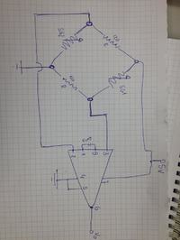
With the data sheet i managed to draw this schematic:

YzjF83m[1].jpg

Is it correct?

I connect 2 or 3 wires to the strain gage? In the schematic there are 2, but all strain gages i saw they had 3 wires coming of...

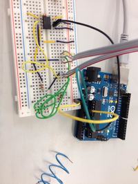
This is how they are now:

idfO503[1].jpg

Sorry if i can't explain better, im a starter and im not a native speaker. Thanks in advance
 
Last edited by a moderator:

hi,
Your circuit looks basically OK, the calculation of 200uA and 100mV are way out.

With a 5V bridge supply you will have a DC level of 5V/2 at the IA [OPA] inputs.

The passive resistor half of the bridge will require careful/fine adjustment if you are to get 'close' to 0V out for no strain.
Also look at the uses of the Vref pin #5 of the IA.
E
 

Hi again guys,

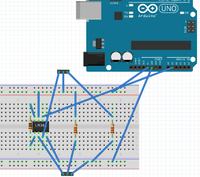
I changed the configuration of the second strain gage, so my sketch is this:

This is what i did here:


The problem is that i now read the tension value in the arduino and the value is always 0, no matter how hard i press it.

Is something missing?

Thanks in advance
 

hi,
Have you checked that as one SG is in tension the other is in compression.?
Also check that the output, in say compression drives the OPA output in a positive voltage direction.

As you are using a single voltage supply it will not be possible to drive the OPA output below 0V.
Typically with 0mV input the OPA output will be at approx +100mV or so.

E

EDIT:
Looking at your latest diagram, what is the resistance value of the strain gauges.?
Also I see no provision for nulling out any bridge zero imbalance.?
If the 120R's are not precisely matched you may have a bridge signal which is trying to drive the OPA below 0V.
 
Last edited:

Hi again, guys.

I have this configuration in the breadboard:


The instrumentation amplifier is the ina122p and not that one. That 3 wires are the 2 strain gages.

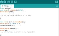
The arduino is running this program:


I read 0.36 or 0.4 (tension) and it doesn't change as i apply load.

If i use the multimeter i read little changes when applied directly to the strain gage.

Can someone help me?

Thanks
 

Hi,

That 3 wires are the 2 strain gages.
Am I missing something? You always need four wires for a strain gauge. 2 for supply and 2 for signals.

Klaus
 

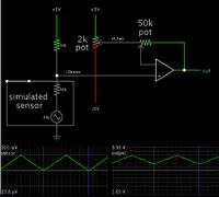
When you think about it, the wheatstone bridge is a difference amplifier.

And the op amp is a difference amplifier.

This common op amp arrangement fulfils the concept of a wheatstone bridge.


Status
Not open for further replies.

Part and Inventory Search

Welcome to EDABoard.com

Sponsor

Back
Top