Continue to Site

Welcome to EDAboard.com

Welcome to our site! EDAboard.com is an international Electronics Discussion Forum focused on EDA software, circuits, schematics, books, theory, papers, asic, pld, 8051, DSP, Network, RF, Analog Design, PCB, Service Manuals... and a whole lot more! To participate you need to register. Registration is free. Click here to register now.

[SOLVED] Arduino Library and MAX7219 led matrix question

Status
Not open for further replies.

wogoos

Member level 2
Member level 2
Joined
Apr 20, 2010
Messages
49
Helped
0
Reputation
0
Reaction score
0
Trophy points
1,286
Activity points
1,909
Dear Reader
I do have a question about a MAX7219 + LED matrix chip and the software Libraries written for it.
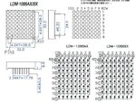
There are two type of these led matrices one like a 1088AX and one like a 1088AX. The difference is the orientation of the LED between the rows and columns. These are reversed in the two AX and BX matrices. The way I look at it is that both matrices can be use in one given design regarding hardware and software libraries used, the only thing that needs to be done is to rotate one matrix 180 degrees compared with the other.
My Question is: Is this assumption right?

I ask this because I'm planning to buy the matrix module from the link below which uses a BX (BS) LED matrix but most of the examples I see make use of a AX (AS) type matrix. I'm worried that the software is not controlling the MAX7219 in a correct way to make the LED's go on and off. That means the LED's need to be forward current activated instead of in reverse. If my assumption is correct I can use the standard libraries without any change. But if I'm wrong I need to change the libraries and I want to avoid that.

Hope some one has experience with it and can let me know
thanks Oscar Goos

https://nl.aliexpress.com/item/Free...rol-module-Special-promotions/1006544892.html
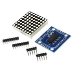
MAX7219-Dot-Matrix-Module-Microcontroller-Module-DIY-KIT.jpg 32mm 8x8 Square Matrix.jpg
 

santoshaxl is right, if you look at the schematic of the individual LEDs, one is common cathode and the other common anode. That means you can't fix it in software, the applied polarity has to be reversed.

Brian.
 

Hi,

In one case ROW is common cathode and COL is common cathode.
In the other case it's the opposite.

Klaus


Hi,

See the "col" of the AX type: aren't there 8 anodes connected to a "common anode"?

--> I still think you can't talk about "common anode or "common anode". I'd say they both can be controlled by the same controller.

Klaus
 

I think in theory it is possible to rotate a matrix display through 90 degrees but the multiplexing through a MAX7219 would make it very difficult to drive. I think you would have to swap the digit drive signals with the segment drives which implies the internal font couldn't be used and it would have to be configured in 64 individual LED mode with alternative segment pattern created by the driver software.

Brian.
 

Hi Brian,
It took a while for me to understand how this chip works and how the MAX7219 interfaces to this matrix. What I did found out is that the MAX is in fact a 7 segments driver intended for 8 digit displays. The MAX connections are grouped in segment control and Digit control. Instead of driving the 7 segments+dot it drives the 8 led's on a column basis. The LED per column are controlled by the segment drivers. The column it self is driven/selected by the Digit control of the MAX. Since the MAX is made only for Common cathode segments of a normal 7 Segment Display this must also be the case for the LED matrix. That's why the LED matrix on a per column basis must be of Common cathode type.
The Columns and rows are not nicely distributed over the 2x8 pinning, they are not mirrored and there for rotating them will not solve the problem. Hope this clears things up.

Thanks for responding

- - - Updated - - -

Hi Klaus,
Thanks for your response, i think you can talk about a common cathode although its a little odd. Also see my response to Brian. The MAX is made for 7 segment type displays these exits in two flavors common cathode and anode. They abuse this MAX to control the individual columns of the led Matrix. The MAX doesn't know if its controlling a 7 segm display or Columns of LEDS from a led matrix. The direction of the leds stays the same if you compare it with a 7 segm display. On a matrix column basis the leds must have a common cathode and are driven on the anode side by the Segment control of the MAX. The meaning of common anode or cathode on the matrix it self is meaningless i agree.
 

It is a clever and versatile IC. Used as an 8-digit driver it automatically decodes the data as a viewable 7-segment font but when driven in matrix mode, the 8 digit drives become column drives and the data bits become row data. So you can show eight 7-segment digits or one 64 dot matrix.

I use them for devices with a two digit numeric display and the remaining 'pixels' used as individual panel indicator LEDs.

Brian.
 

Status
Not open for further replies.

Similar threads

Part and Inventory Search

Welcome to EDABoard.com

Sponsor

Back
Top