boylesg
Advanced Member level 4

- Joined
- Jul 15, 2012
- Messages
- 1,023
- Helped
- 5
- Reputation
- 10
- Reaction score
- 6
- Trophy points
- 1,318
- Location
- Epping, Victoria, Australia
- Activity points
- 11,697
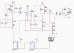
I am following this: https://electronoobs.com/eng_arduino_tut10_3.php
Using this code based on the authors code:
The circuit that the author specifies absolutely does not work - there is no response to the call to pulseIn(....)
However if a remove the connection from the bottom of the tank circuit to GND then there is a response to the call to pulseIn(....)
If I connect a 150R resistor between the tank circuit and GND then there is intermittent responses to pulseIn(....).
If I connect a 10k resistor between the tank circuit and GND then there is always a response to to pulseIn(....) but the pulse period, and therefore the calculated capacitance value, is unstable and varies widely between 0.01uH to 3uH (roughly) for a 10uH inductor.
If I connect a 1M resistor between the tank circuit and GND then there is always a response to to pulseIn(....) and the pulse period, and therefore the calculated capacitance value, is fairly stable and varies between 2uH to 10uH (roughly) for a 10uH inductor.
What is going on here?
Using this code based on the authors code:
Code:
#include <Wire.h>

//13 is the input to the circuit (connects to 150ohm resistor), 11 is the comparator/op-amp output.
double frequency, capacitance, inductance;
uint32_t nPulse = 0;
void setup()
{
  Serial.begin(115200);
  pinMode(11, INPUT);
  pinMode(12, OUTPUT);
  delay(200);
}
void loop()
{
  digitalWrite(12, HIGH);
  delay(100);//give some time to charge inductor.
  digitalWrite(12,LOW);
  //delayMicroseconds(100); //make sure resination is measured
  nPulse = pulseIn(11,HIGH,5000);//returns 0 if timeout
  if(nPulse > 0){ //if a timeout did not occur and it took a reading:


  // #error insert your used capacitance value here. Currently using 2uF. Delete this line after that
  capacitance = 10.0; // - insert value here


  frequency = 1/(2*(float)nPulse);
  inductance = 1/(capacitance*frequency*frequency*4*3.14159*3.14159);//one of my profs told me just do squares like this

  //Serial print
  Serial.print("High for uS:");
  Serial.print( nPulse );
  Serial.print("\tfrequency kHz:");
  Serial.print( frequency * 1000);
  Serial.print("\tinductance uH:");
  Serial.println( inductance );
  delay(500);

  }
}
The circuit that the author specifies absolutely does not work - there is no response to the call to pulseIn(....)
However if a remove the connection from the bottom of the tank circuit to GND then there is a response to the call to pulseIn(....)
If I connect a 150R resistor between the tank circuit and GND then there is intermittent responses to pulseIn(....).
If I connect a 10k resistor between the tank circuit and GND then there is always a response to to pulseIn(....) but the pulse period, and therefore the calculated capacitance value, is unstable and varies widely between 0.01uH to 3uH (roughly) for a 10uH inductor.
If I connect a 1M resistor between the tank circuit and GND then there is always a response to to pulseIn(....) and the pulse period, and therefore the calculated capacitance value, is fairly stable and varies between 2uH to 10uH (roughly) for a 10uH inductor.
What is going on here?
Last edited:


