krazyfencer
Junior Member level 2

- Joined
- Aug 5, 2013
- Messages
- 23
- Helped
- 0
- Reputation
- 0
- Reaction score
- 0
- Trophy points
- 1
- Location
- East Coast, USA
- Activity points
- 266
Hello,
I am trying to create a really basic pre-amplifier as a first step of constructing an AM receiver. The first problem that I have encountered is adding a dc offset to the small signal ac input to bias the transistor in the pre-amplifier into the linear range. I hope that made sense, I'm really just getting into electronics. I read in a previous thread (circa 2005) by tofinhk that you want to add a capacitor between the ac input and the dc source.
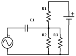
Here is what I've currently got (where R3 would actually be the base of the transistor amplifier):

My questions:
1) is this a reasonable way to add a dc offset to an ac source?
2) is the capacitor there to prevent the dc current from going into the ac source?
3) are the ac source (in my case an antenna) and dc source supposed to share a common ground?
4) do you need an inductor to prevent the ac source from going into the dc source?
I hope this doesn't read too long, I am as new to forums as electronics. Thanks for the help!
I am trying to create a really basic pre-amplifier as a first step of constructing an AM receiver. The first problem that I have encountered is adding a dc offset to the small signal ac input to bias the transistor in the pre-amplifier into the linear range. I hope that made sense, I'm really just getting into electronics. I read in a previous thread (circa 2005) by tofinhk that you want to add a capacitor between the ac input and the dc source.
Here is what I've currently got (where R3 would actually be the base of the transistor amplifier):

My questions:
1) is this a reasonable way to add a dc offset to an ac source?
2) is the capacitor there to prevent the dc current from going into the ac source?
3) are the ac source (in my case an antenna) and dc source supposed to share a common ground?
4) do you need an inductor to prevent the ac source from going into the dc source?
I hope this doesn't read too long, I am as new to forums as electronics. Thanks for the help!

