Continue to Site

Welcome to EDAboard.com

Welcome to our site! EDAboard.com is an international Electronics Discussion Forum focused on EDA software, circuits, schematics, books, theory, papers, asic, pld, 8051, DSP, Network, RF, Analog Design, PCB, Service Manuals... and a whole lot more! To participate you need to register. Registration is free. Click here to register now.

Anyone konw this circuit in the attachment?

Status
Not open for further replies.

icsoul

Member level 3
Member level 3
Joined
Nov 28, 2005
Messages
66
Helped
2
Reputation
4
Reaction score
0
Trophy points
1,286
Activity points
1,703
What kink of circuit it is ?

How to analysis its transfer function?


I want to get some stuff for this circuit.

Thanks !~
 

Taking into account first order effects only the transfer function is
v(outn)/v(inp)=Gm*Routn, v(outp)/v(inp=Gm*Routp, here Gm=(1+sRC)/R
 

A similar circuit is commonly used to remove the long tail in gaseous detectors for high energy particles. It's called a shaper there, or tail cancellation amplifier.

There's a description of such a circuit in here ,
http://dx.doi.org/10.1016/j.nima.2006.02.168
and the concept is explained here
**broken link removed**
a chip implementing this appears here,
**broken link removed**
look for the shaper section.

hope this helps.
 

used to extend bandwidth of gm
 

Alex_IC said:
Taking into account first order effects only the transfer function is
v(outn)/v(inp)=Gm*Routn, v(outp)/v(inp=Gm*Routp, here Gm=(1+sRC)/R


Alex_IC:

Could you explain how to get this transfer function?

Added after 5 minutes:

n1cm0c said:
A similar circuit is commonly used to remove the long tail in gaseous detectors for high energy particles. It's called a shaper there, or tail cancellation amplifier.

There's a description of such a circuit in here ,
http://dx.doi.org/10.1016/j.nima.2006.02.168
and the concept is explained here
**broken link removed**
a chip implementing this appears here,
**broken link removed**
look for the shaper section.

hope this helps.

I can not access the first URL.
This circuit is used to compensate high frequency loss.
Now I want to know is that what's the operation principle, how to analysis, and what's the type(name) of this circuit?

Whatever, thank you very much!~

Added after 5 minutes:

hunk said:
used to extend bandwidth of gm

hi, hunk

Could you explain this in more detail?

Thanks!~
 

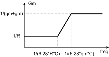
We can assume that gm>>1/(2*R), so that at low freq (where Cap is negligible) the effective transcondactance of the DiffAmp is Gm=1/R. At high freq the Cap shunts the R, and effective transcondactance is Gm=1/(gm+gm).
92_1205991868.gif


So more accurate eqation is

v(out)/v(inp)=(Rout/R)*[(1+RCs)/(1+gmCs)]
 

    icsoul

    Points: 2
    Helpful Answer Positive Rating
Alex_IC said:
We can assume that gm>>1/(2*R), so that at low freq (where Cap is negligible) the effective transcondactance of the DiffAmp is Gm=1/R. At high freq the Cap shunts the R, and effective transcondactance is Gm=1/(gm+gm).

92_1205991868.gif


So more accurate eqation is

v(out)/v(inp)=(Rout/R)*[(1+RCs)/(1+gmCs)]

Thank you, Alex_IC!

It is very helpful!~
 

This circuit is called amplify with high freauency boost.
 

This circuit also has the advantage of degenration without an IR drop and having more headroom. The disadvantage is that it has higher noise due to current sources noises which are not common so the noise is uncorrelated at the Gm's output. The circuit is used to have broadband amplification where at high frequency the capacitive load dominates the output impedance and so the Gm will get higher to have the same gain.
 

cdz said:
This circuit is called amplify with high freauency boost.

Hi,cdz

Do you have some good stuff about this?

Added after 2 minutes:

Jim cage said:
This circuit also has the advantage of degenration without an IR drop and having more headroom. The disadvantage is that it has higher noise due to current sources noises which are not common so the noise is uncorrelated at the Gm's output. The circuit is used to have broadband amplification where at high frequency the capacitive load dominates the output impedance and so the Gm will get higher to have the same gain.

Hi, Jim cage

Could you recommend some material about this topic?
 

Status
Not open for further replies.

Part and Inventory Search

Welcome to EDABoard.com

Sponsor

Back
Top