Continue to Site

Welcome to EDAboard.com

Welcome to our site! EDAboard.com is an international Electronics Discussion Forum focused on EDA software, circuits, schematics, books, theory, papers, asic, pld, 8051, DSP, Network, RF, Analog Design, PCB, Service Manuals... and a whole lot more! To participate you need to register. Registration is free. Click here to register now.

Any ideas how I'd convert this transmitter board from 315 mhz to 433 mhz?

Status
Not open for further replies.

waldvogelmj

Newbie level 6
Newbie level 6
Joined
Nov 16, 2017
Messages
12
Helped
0
Reputation
0
Reaction score
0
Trophy points
1
Activity points
89
Hi guys, new member here.

I'm working on a little project with car remotes and need to convert a US transmitter board to Euro spec, from 315 mhz to 433 mhz. I know it's not as simple as changing the SAW filter (this filter says R2622 while the OEM Euro boards are R2633). Does anyone here have any thoughts on what other components I need to swap out to make this conversion?

Thanks in advance
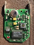
IMG_1716.jpg
 

Changing the SAW resonator should do it. The antenna is slightly shorter at 433MHz so if there is an open ended track running from near the SAW on the other side of the board you could trim it slightly.

However, i'm not sure what you aim to achieve as the coding method is different from one transmitter to another so unless you have the matching receiver and serial number just changing the frequency is pointless.

Brian.

Thanks for your reply. I currently have both a 315mhz and 433 mhz receiver for this system. I can swap the 93C46 chips between US and Euro transmitter boards and the data on the chip works in either system.I was guessing whatever is on the microprocessor (which I can't read) was the same with both versions.

I program these things for 1990's cars to help people replace key fobs that are difficult to find. I can still buy the US version new but the Euro version is in short supply and no longer available new. Since the programming appeared to me to be the same between versions, I thought I could potentially buy US versions and convert them to Euro.

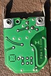
Here's a picture of the back.

IMG_1717.jpg
 

I forgot to say in the last reply that I did swap SAW resonators years ago and that alone didn't seem to work. I didn't have the receivers to test them however like I do today so maybe I should try that again.
 

There may be some capacitor values slightly different too but changing the SAW resonator should be sufficient. The antenna is the 'U' shaped track with the part number inside it. Note it is double sided. If it works with just the SAW replaced I would be inclined to leave the rest alone. The range may be slightly shorter than normal but probably still adequate. To optimize it, you would have to shorten the right side of the 'U' as shown in post #4 by about 20% (on both sides of the PCB) but the exact best length would have to be found by experimentation.

Brian.

Ok thanks. If I needed to swap some capacitors would it be obvious which ones to look at? Also, can I ask why are there some solder joints on the antenna? If I need to cut it below these joints does that cause a problem?

Thanks again
Mark
 

The SAW resonator is part of a single transistor oscillator. It works much like a conventional quartz crystal but SAW technology allows higher frequencies than are practical to fabricate in quartz. The feedback capacitor values depend to a degree on the frequency and may, for example change from 10pF to 8.2pF to maintain best stability but you would have to trace the schematic and find the SAW data sheet to get best values. As I said earlier, I doubt the original values are far enough different to optimal ones to make much difference.

The via holes are just to link the antenna tracks, you need to shorten the open end of the tracks on both sides of the PCB but it will take trial and error to find the best length. It will only effect the range of the unit so before undertaking surgery I suggest you check if it is adequate already. If it needs shortening, use a scalpel to make a fine slit through the tracks and repeat at say 1mm intervals while checking the range.

Brian.
 

Old topic. I was able to purchase some Euro frequency versions so didn't bother going through all the work to convert from 315 to 433. Changing the SAW resonator alone wasn't enough.

Does anyone have a thought which component would be the culprit if a transmitter were to pulse? I have a bad one where the LED goes from bright to weak and the reading goes on and off on the frequency meter. I'm trying to fix for someone and so far have only tried swapping the SAW resonator and battery with no success.
 

Haven't you thought about doing a survey of the schematic drawing of this circuit? It does not seem so complex, would not take more than 20-30 minutes to achieve; this would turn it easier to analyze the system as a whole.
 

Status
Not open for further replies.

Part and Inventory Search

Welcome to EDABoard.com

Sponsor

Back
Top