FvM, since you asked...
Description of the Transmitter Electronics
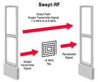
Each transmitter electronics is able to feed one LUCATRON antenna with a swept HF signal of
8.2 MHz. In order to avoid disturbances between the emitted HF signals, synchronization with other
transmitters must be guaranteed.
The standard version of the Aquila TX board allows the 85 Hz sinusoidal modulated 8.2 MHz HF
carrier signal to be:
− generated locally (oscillator circuit for master applications), or alternatively
− to be regenerated from an optically received swept HF signal of another TX (opto receiver for
slave applications).
The bi-opto version of the Aquila TX additionally allows the onboard generated (master) or received
and then regenerated (slave) swept HF-signal to be converted and optically transmitted in order to
synchronize additional transmitters.
The two opto transmitters used in the bi-opto version allow:
− a master transmitter to synchronize two other optically slaved (and possibly repeating) transmit-
ters.
− an optically slaved transmitter to be used as repeater to synchronize two other optically slaved
transmitters.
By using 3 bi-opto transmitter boards (TX) (one used as synchronization master and two as
synchronization repeaters) and 4 standard TX (as synchronization slaves), clusters of up to 7 TX
may be synchronized. This way up to 7 checkout or 14 exit-gates (in a row) may be configured with-
out need of a master rack.
Since the optically transmitted synchronization signal may be repeated only once, a master rack still
has to be used if more than seven transmitters have to be synchronized.
A block diagram and of the Aquila TX board are shown on the next pages. The board consists of a
digital part, an analog part and a power supply / filter part.
The standard version of the Aquila transmitter is fully equipped with the exception of the two optional
opto transmitters. It can be used as a master-TX for small installations (single or dual gates
equipped with one TX only) or as slave-TX for all larger applications.
The bi-opto version of the Mark 4 transmitter board is almost identical to the standard version. The
only difference is that the two opto transmitters (IR-LED's) are already mounted. The bi-opto TX
board can be used as a master-TX in medium installations (2 to 7 TX) or as synchronization signal
repeating slave-TX for medium to very large installations.

Receiver Electronics
The receiver board consists of a:
- Analog Part
- Digital Part
- Power / Alarm Part
1.1. Analog Part
The first input stage amplifies the received RF signal. If this signal is too large, the gain of the first
input stage can be reduced using jumper J4 (Narrow or Wide position).
The next stage is a band-pass filter having a frequency range between 7.2 to 9.2 MHz. If necessary,
the gain of the RF amplifier following the band-pass filter can be changed with potentiometer R112
(RF-Gain). An AGC is not built in, this gives a controlled RF amplification. The amplitude of the tag
signal is pre-regulated by a fixed resistor. The DSP synchronization is done through "air", that is
extracted from the received transmitter signal. A beat note circuit is implemented. This circuit is
inhibiting spikes, radio transmitters and other signals with a very high Q factor.
1.2. Digital Part
The analog tag signal is A/D converted and sampled. The DSP (40MIPS) filters the demodulated LF
signal and stores the result in a memory. It processes this data and if all alarm criteria are met, it
triggers an alarm.
DIL and rotary octal switches allow adjusting the software parameters and test positions.
1.3. Power / Alarm Part
Power is supplied to the receiver electronics by applying 20-26 VDC or 18-20 VAC to the power
supply/power filter part. The integrated filter is used to reduce any interference picked up on the
incoming line from the power supply.
An audible alarm (buzzer) is mounted on the filter part. Outputs for the antenna lamp and an exter-
nal alarm are provided.
The volume of the buzzer is adjustable with the Volume potentiometer (R426). A jumper (J10) on the
filter part allows setting the buzzer for continuous or intermittent tone. The duration of the audible
alarm is about 2 seconds. The duration of the alarm light is about 10 seconds.

And there are also Antenna matching circuit description to which is missing.
Antenna board:

And here not everything is clear yet. Antenna board connects to two loops. Each loop through it's own transformer. there is a capacitor for each loop to complete the tank and tuning cap - just one. 200 Ohm resistor on the output. I'd love to understand this board fully. Any hints?


