ArticCynda
Advanced Member level 1

Hi all,
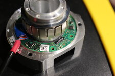
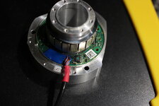
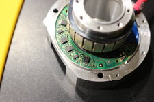
I have a defective KUKA LBR IIWA robotic manipulator, with suspected angular encoder failure in one of the joints. After disassembly of the motor unit which contains BLDC, brake, and angular encoder, I managed to retrieve the encoder board shown in attachment. Unfortunately I can't figure out how it works...
There is no text on the PCB so I don't have a part number or datasheet for it. The only package with an identifiable part number is a FM24CL16B serial FRAM memory chip in SOIC-8 package from Cypress, but there is no visible MCU on the board that could be communicating with it. There is a 14 pin connector on the data cable, the other side appears to be soldered directly to the PCB and covered in a blue epoxy. There are also 4 identical TSSOP-8 packages which I suspect may be dual opamps. The magnet ring in the picture is part of the BLDC and is normally shielded, so I'm fairly certain the angular encoder does not rely on magnetic fields from the magnets for positioning. There is however a ring that appears to ferrite or similar material, non-magnetic, that the PCB fits perfectly around, and this ring is fixated to the rotating shaft. There are a further 4 black epoxy drops in pairs (on top and bottom side of the PCB) on the inner edge that appear to hide an active component that is likely doing the "magic", as there is a visible fanout of traces around these epoxy drops. The ring it appears to make contact with, does not have any visible grooves or similar characteristics.
Does anyone recognise an angular encoder like this? What is the underlying principle it is based on (magnetic, optic, ...)? And what is the transducer hidden under the black epoxy droplets?
Any ideas or leads are much appreciated!
Best regards,
AC


