Continue to Site

Welcome to EDAboard.com

Welcome to our site! EDAboard.com is an international Electronics Discussion Forum focused on EDA software, circuits, schematics, books, theory, papers, asic, pld, 8051, DSP, Network, RF, Analog Design, PCB, Service Manuals... and a whole lot more! To participate you need to register. Registration is free. Click here to register now.

analog filter without capacitor

Status
Not open for further replies.

0987654321

Newbie level 3
Newbie level 3
Joined
May 29, 2013
Messages
3
Helped
0
Reputation
0
Reaction score
0
Trophy points
1,281
Activity points
1,303
can somebody tell me that how to by pass the A.C signal from a A.C +D.C signal
such that there should not be any time lag between input signal and the output signal,
which means its not supposed to use capacitor.

A.C signal frequency is of range 8-80 hz.

Is there any method to take only the a.c signal retaining the d.c behind with time lag.

plz help me..

here is the link of figure.

https://obrazki.elektroda.pl/2897723500_1369826637.jpg[/U]

This scheme removes DC without passing the signal through it:

https://www.edn.com/design/analog/4...ection-range-of-differential-dc-input-voltage

Of course, instrumentation amplifiers are not known for their incredibly fast slew rates, so that'll be your limiting factor.
 
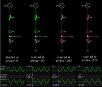
You can use a capacitor in a high pass filter to block the DC (I don't offhand know how do that without a capacitor somewhere in the circuit). You just have to make the low frequency rolloff low enough (RC time constant high enough) so that the phase shift is negligible at 8Hz.
 
The series capacitor will introduce leading effect, rather than lagging. (That is, for a sine-like signal).

A carefully selected value will charge to the DC level within a fraction of a cycle, while admitting AC immediately.
It matters only slightly what is the starting point in the cycle.
The signal is attenuated slightly.

Screenshot:

 
The only way to amplify the DC + AC signal and subtract the DC without delay is to know beforehand what the DC level will be. Then put that DC level into one input of a differential amplifier and the combined signal into the other input.
 
again it will give a lag in time synchronization

- - - Updated - - -

That s right., but in my case the d.c is not a constant for a time period,
it is varying like 5mv,6mv,7mv,8mv...15mv.

at all these instants a.c value is a constant ,suppose (-0.5 to +0.5)mv .
 

To clarify, do you want to preserve the DC or AC component of the signal?
again it will give a lag in time synchronization

- - - Updated - - -

That s right., but in my case the d.c is not a constant for a time period,
it is varying like 5mv,6mv,7mv,8mv...15mv.

at all these instants a.c value is a constant ,suppose (-0.5 to +0.5)mv .
So if your "DC" is changing over time, it's no longer DC, it's a signal with a low frequency AC component. So you, by definition, need a filter. All filters have some finite group delay which you will have to tolerate, because we live in a causal universe.

One way to do this is to use an integrator in a feedback loop to cancel out the DC component. See the following:
https://www.edn.com/design/analog/4368992/Use-an-integrator-instead-of-coupling-capacitors
No matter how you formulate it, this is still a filter and will cause group delay in the signal(s).
 
Status
Not open for further replies.

Similar threads

Part and Inventory Search

Welcome to EDABoard.com

Sponsor

Back
Top