Continue to Site

Welcome to EDAboard.com

Welcome to our site! EDAboard.com is an international Electronics Discussion Forum focused on EDA software, circuits, schematics, books, theory, papers, asic, pld, 8051, DSP, Network, RF, Analog Design, PCB, Service Manuals... and a whole lot more! To participate you need to register. Registration is free. Click here to register now.

An old exam problem related to an amplifier

Status
Not open for further replies.

Wow_01

Newbie
Newbie level 4
Joined
Sep 19, 2019
Messages
5
Helped
0
Reputation
0
Reaction score
0
Trophy points
1
Activity points
54
Hi,

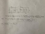
I'm trying to solve an old exam problem, which i've attached below, and need to know if I've done it correctly (I don't think I have since I've not used r0 as stated I should in the problem). Could someone please help me with this, I would really appreciate it :smile:

Problem:
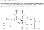
Screenshot 2020-05-12 at 10.47.37.png

My solution:
IMG_4282.jpg

Thanks in advance!
 

It seems correct to me (in you solution R1=RG, R2=RA), but you should also include r0. This is simply a resistor placed between D and S, then is in parallel with RD and RL.
 

I don't know why I wrote R1 and R2.
Ok, nice. Thanks for the help!
 

The input impedance is not RG//RA (it is much higher) because RG is bootstrapped with positive feedback from RA.
 

Due to the presence of the (ideal) infinite capacitance capacitor, in parallel with Rs, all frequencies but DC are shunted to ground. Then there is no positive feedback through RA
 

I have to side with AudioGuru on this one. Are we talking about DC resistance or AC impedance?

It is correct that for the AC analysis the source resistor would be completely shunted away by the infinite capacitor in parallel with it....in which instance the problem would require to find the input impedance, not the input resistance.

In other words, the problem statement is confusing. It should have stated to find the input and output impedance of the circuit, even though that impedance for all frequencies other than DC, the magnitude of Zeq = Req, and the angle would approach zero.


I know that I am sounding pedantic, but a prof actually screwed me, over 46 year ago, precisely with a very similar problem statement.
 

I was wrong because I did not see the source capacitor, which might have been added later to increase the gain.
 

There is no AC but DC Feedback.Analysis seems correct for AC only..
 

I have to side with AudioGuru on this one. Are we talking about DC resistance or AC impedance?

It is correct that for the AC analysis the source resistor would be completely shunted away by the infinite capacitor in parallel with it....in which instance the problem would require to find the input impedance, not the input resistance.

In other words, the problem statement is confusing. It should have stated to find the input and output impedance of the circuit, even though that impedance for all frequencies other than DC, the magnitude of Zeq = Req, and the angle would approach zero.


I know that I am sounding pedantic, but a prof actually screwed me, over 46 year ago, precisely with a very similar problem statement.

The OP talk about "small signal parameter", then DC biasing is not involved in the analysis.
 

Status
Not open for further replies.

Part and Inventory Search

Welcome to EDABoard.com

Sponsor

Back
Top