Continue to Site

Welcome to EDAboard.com

Welcome to our site! EDAboard.com is an international Electronics Discussion Forum focused on EDA software, circuits, schematics, books, theory, papers, asic, pld, 8051, DSP, Network, RF, Analog Design, PCB, Service Manuals... and a whole lot more! To participate you need to register. Registration is free. Click here to register now.

Amplifying Wi-Fi signal to extend range

Status
Not open for further replies.

JuanJuan

Junior Member level 1
Joined
Jan 5, 2016
Messages
19
Helped
0
Reputation
0
Reaction score
0
Trophy points
1
Activity points
181
Hello everyone. I'm trying to do something like this:
https://www.amazon.com/TP-LINK-Wi-F...8&qid=1454454779&sr=1-2&keywords=wifi+booster

for a university project, but I can't find the information I need. I'm not from any English speaker country, so maybe I'm searching in a wrong way, because I only find some basic ways to extend wifi (like putting a can around the router).

Can anyone help me?
Thanks!!!!!

- - - Updated - - -

I need the project to be absolutely ANALOG. Is that possible?
 

Re: [moved] Help with wifi booster

Hello! What you are looking for its named Power Line Communication. It is a real challenge, because you need to establish a communication through the power line with the modem and then, you need to have the proper hardware to send the signal, as any transmitter.

Hope will help!
Best regards
Jesus
 

Re: [moved] Help with wifi booster

Hey!! I see with more attention the product and I see that it is not a PLC. It is a wifi repeater.

Sorry!!
Best regards
 

Yes, it's a wifi repeater, not a PLC.

**broken link removed** is how the WiFi repeater works:

devolo-WiFi-Repeater-scenario_devices-xl-3271.jpg

But I can't find ANY information. I've been searching for more than 5 hours and I didn't find one circuit design
 
Last edited by a moderator:

Hello everyone. First of all, I want to tell you that I chat with BradtheRad and I'm posting a new thread in this subforum with more information. Please, do not move it to another subsection.

I have to make an ANALOG (completely analog) project for University and I thought it would be great to make a Wi-Fi Range Extender. I studied a lot about all type of amplifier configurations and I think I can use that information to build this project.
My problem is that I can't find ANYTHING about how to make it, so I don't know from where do I have to start.
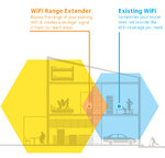
This is what I want to do:
wifi.jpg

Using what I studied in the last months, I suppose it works like this:
I receive a Wi-Fi signal (I don't know if I can use the Wi-Fi signal or how does that work), I put it in an amplifying system (I know all configurations (Darlington, Cascode, etc.) but maybe there's another one better) and at the output I have the same signal but amplified, so it has to make the Wi-Fi range larger, like the Figure shows.

What do you think? I don't have any project or "diy" to see because I couldn't find anyone, but if I put in amazon "wifi amplifier" I find a lot of devices, like this: https://www.amazon.com/TP-LINK-Wi-F...qid=1454536503&sr=1-2&keywords=wifi+amplifier


Thanks!!!
 

Even if your design is a purely analog circuit, it should be clearly posted in the RF section. Because it also refers to information that has been posted before, you should not start a new thread.

- - - Updated - - -

You should consider that WiFi range extenders like the TPLink device are digital repeaters. It's not completely impossible to make an analog repeater but rather difficult. In contrast to GSM phones, WiFi doesn't use separate up- and downlink bands. Means that you need directional couplers with high directivity and very good directional antennas.
 

Thanks FvM. That was the kind of things I need to know.

So I have to stop with this project :cry:

Is there any other project that you think would be nice to do? It has to be all analog (for example, a friend of mine did a theremin)
 

Is there any other project that you think would be nice to do? It has to be all analog (for example, a friend of mine did a theremin)

Wireless energy transfer would be a nice one:-D
 

Wireless energy transfer would be a nice one:-D

That's nice!!! I investigated about walkie talkies and different types of wireless communication but wireless energy transfer is more interesting :D (as you can see, I'm trying to get involved in the wireless world)

The only problem is that I only find some papers about that but not a project to build (for example, I think of a wireless charger for my laptop, but it can be something smaller)

I mean, all I find are big coils that use magnetic fields, but I need to make a project using transistor and/or amp ops.
 
Last edited:

Thanks FvM. That was the kind of things I need to know.

So I have to stop with this project :cry:

Is there any other project that you think would be nice to do? It has to be all analog (for example, a friend of mine did a theremin)

You're quitting just like that? The circuit you are describing is very possible to design, and you can find them on the market. This thread is discussing your problem:

https://www.edaboard.com/threads/349914/

Aside from the circuits discussed here, with a solid understanding in electronics, you can come up with your own designs to accomplish bi-directional amplification.


regards,
Aaron


EDIT: I just re-read your post. Are you trying to pick up a signal and then re-transmit it, or are you just trying to boost the signal? If you are trying to re-transmit it, then I agree that you are gonna have a hard time...
 
Last edited:

I'm trying to re-transmit it, because I think that's what I have to do to reach a larger place. I couldn't find what's different between a booster and a re-transmitter.
I quit because I don't have any information.

I have solid understanding in Electronics, but I don't have too much time (I mean, I can't be 3 months doing this, I have time to do this: find a project done on Internet, understand it perfectly (I have really good professors and they want you to understand EVERYTHING perfectly) and build it)
 

I'm trying to re-transmit it, because I think that's what I have to do to reach a larger place. I couldn't find what's different between a booster and a re-transmitter.

re-transmitting was also my understanding, that's why I mentioned directional antennas. The difference is simple, a booster can be connected to the antenna jack of a WiFi device (if it has one, which will be already a problem in many cases), a re-transmitter picks the signal from air at a certain distance and transmits it to the peer(s), and vice versa.

A booster usually involves automatic RX/TX switching controlled by the output level of the transmitter to be boosted. That's relative easy for a VHF voice transceiver but already difficult for a WiFi transceiver with µs packet times.
 
Wireless energy transfer is not so much an RF problem IMO...its more a power electronics problem, unless you are talking far field energy transfer. Even then its atypical.

Why not build an FM radio? Some fundamentals to be learned there, plus u get to do field tests.

Aaron
 

Why not build an FM radio? Some fundamentals to be learned there, plus u get to do field tests.

Aaron

I searched a lot about FM radios, and the other thing I would like is a transmitter (I thought: "if I make a transmitter and a receiver, I have a walkie talkie" haha). But it would be better if now I make an FM radio receiver and in a pair of months I try to make something bigger.

For the FM radio, I read that it's very difficult to make the PCB because it has to be perfect, and all the designs I saw had some tricks.

For example, I read about these:
- Here are two that are the most known: **broken link removed** (I think that the first is easier to build and understand, what do you think?)
- Single transistor FM radio: https://www.homemade-circuits.com/2013/10/make-this-simple-fm-radio-circuit-using.html (I never in my life saw a capacitor from emitter to collector)
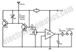
- I also found this one:
small-fm-radio.jpg
in this website: https://www.electroschematics.com/5150/tiny-fm-radio/ but it has too little explanation.

There are a lot of FM radio projects and I really would like to make it, but I would need to know which one works better, which one can be explained better, and what things do I have to be careful with when I build it.

Do you have any experience in this field? Can you help me?
Thanks!
 

Then links you supplied are for superregenerative receivers. As the point is to learn, i would recommend building a standard superheterodyne receiver. Most receivers on the market follow it. You can treat it as a system design and buy an LNA, a Mixer, vco, filters etc, or u cld even design your own subcircuits.

Aaron
 
There are a lot of FM radio projects and I really would like to make it, but I would need to know which one works better, which one can be explained better, and what things do I have to be careful with when I build it.

Do you have any experience in this field? Can you help me?
Thanks!

I purchased an FM transmitter kit from an electronics mail-order house. I followed a schematic to solder a couple dozen parts onto a pcb. Power was from a 9V battery.

It worked fine once I picked up the transmission. I spoke into the included electret mic. A nearby FM radio received the signal. I had to tune both items to an unused area of the commercial FM band.

The kit included a simple rf field strength detector. It consisted of simple discrete parts which I soldered together and hooked up to my VOM.

Such kits are instructive to show what's possible.

Can you please give me the instructions of the kit, the circuit design, etc.?

- - - Updated - - -

Then links you supplied are for superregenerative receivers. As the point is to learn, i would recommend building a standard superheterodyne receiver. Most receivers on the market follow it. You can treat it as a system design and buy an LNA, a Mixer, vco, filters etc, or u cld even design your own subcircuits.

Aaron

Thanks Aaron!!

I couldn't find any circuit design. For example, this website explains but doesn't show me how to make it: **broken link removed**

This one is really good but doesn't show me the circuit design: https://www.radio-electronics.com/i...heterodyne-radio-receiver/basics-tutorial.php

:???:
 

What kind of equipment do you have available? How about PCB design, do you have any means to fabricate a PCB, or is this going to be veroboard/breadboard. What about budget for purchasing components? Do you have a signal generator that goes up to 100 MHz for debugging, and a spectrum analyzer? Just trying to find out the limitations of the project. Also how much time do you have? Just 2 months?


Aaron
 

Can you please give me the instructions of the kit, the circuit design, etc.?

It looked sort of like this. Many similar schematics are on the internet. Some have fewer parts, some more.


You would do best to obtain a kit. Its frequency is more likely to land within the commercial FM band. If I had tried to build it on my own from scratch, I'm not sure I would have been successful. I wouldn't have known for certain if it was oscillating or not. And if I had not been able to pick it up on my FM radio easily, I wouldn't have known which way to turn the adjustment. Etc.
 

What kind of equipment do you have available? How about PCB design, do you have any means to fabricate a PCB, or is this going to be veroboard/breadboard. What about budget for purchasing components? Do you have a signal generator that goes up to 100 MHz for debugging, and a spectrum analyzer? Just trying to find out the limitations of the project. Also how much time do you have? Just 2 months?


Aaron

Aaron, I have 2 or 3 weeks. We're 3 people, so I think we can do it right.
We have a wave generators, oscilloscopes, etc. because we can go to the University to do it. I don't have too much experience in PCB design, but I can do the design with the printer, the smoothing iron, etc. If it's better, there's a place in my University where they do the PCBs perfectly

My idea is to make all the simulations (using LTSpice or Orcad) this weekend, buy all the components, make the project in a breadboard first and see if it works, and then in a PCB. If it's better to do it in PCB, I can do it there without trying first a breadboard.

I know it's too little time, but we're 3 people and we can make a lot of effort to make that possible.
 

Status
Not open for further replies.

Part and Inventory Search

Welcome to EDABoard.com

Sponsor

Back
Top