Continue to Site

Welcome to EDAboard.com

Welcome to our site! EDAboard.com is an international Electronics Discussion Forum focused on EDA software, circuits, schematics, books, theory, papers, asic, pld, 8051, DSP, Network, RF, Analog Design, PCB, Service Manuals... and a whole lot more! To participate you need to register. Registration is free. Click here to register now.

Aluminium PCB trace width

Status
Not open for further replies.

snipex

Junior Member level 3
Joined
May 23, 2016
Messages
29
Helped
2
Reputation
4
Reaction score
2
Trophy points
3
Activity points
284
Hi

I'm currently working on a BLDC inverter and I need better cooling of SMD MOS-FETs.
I'm looking into aluminium PCBs and I cant find a guideline or a calculator that shows me how wide the traces must be for a given current.
PCB will be mounted on a heatsink.
I need 100A peak for 1-2s and 30A constant current.

Side question: Has anybody worked with aluminium PCB that then transfers current to a FR4 board? I'm looking into SMD high current jumpers but I can't find any.
They have to be 20mm in length.
 

Aluminium as in a aluminium core and copper outer layers\traces?
or aluminium core and outer traces?

An interesting question that I look forward to someone being able to answer.
 

I never heard about aluminium PCB traces and can hardly see a purpose of it: no additive galvanic processing, no soldering of regular electronic components possible.

The term "aluminium PCB" is commonly used for aluminium core.

- - - Updated - - -

O.K. they exist, but apparently for very special applications, with bond interconnect.
 

For many years, there have been alumina ceramic substrates for high power applications. They have good thermal conductivity, electrical insulation and can withstand higher temperatures than FR4.

And they are usually attached to the heatsink itself.

Are you sure you are not confusing alumina with aluminum?
 

I'm thinking about aluminium (or alumina. Not sure as everyone writes aluminium) core PCB.
Every high power LED application uses this.

Picture of what I'm thinking about:
Layers1-1024x587.png

I found this (page 9 : 4.0 Maximum Copper Foil Current ):
https://www.bestpcbs.com/design-guide/T-guidePart1.pdf

Does this seem right to you?
The numbers seem very high to me.
 
Last edited by a moderator:

Ok I got you...insulated metal substrate boards.
In a company which manufactured power supplies, we used to employ these in our higher powered products.

The current transfer from IMS board to the FR4 main board was achieved with solid copper posts. These posts had been custom stamped and formed from a solid copper wire, and then tin-plated for corrosion protection and solderability. The tin plating may have had an organic layer that protected them from humidity and which would vaporize during reflow solder.
 
  • Like
Reactions: snipex

    snipex

    Points: 2
    Helpful Answer Positive Rating
I'm probably asking to much but do you happen to have a picture of what this looks like?
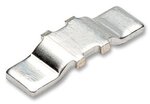
I'm thinking of making something like this but bigger:
2210347-40.jpg
 

Sorry, I worked for that company around 2001-2003. But I can describe it to you.

Our design was two stacked boards (FR4 and IMS), one on top of each other. The lower one was the IMS which was securely attached to a large heat sink.
The top one was the FR4 where all of the control circuit was installed.

Connection between the two was for the small signals (gate drive, thermistor sense, etc) via an off-the-shelf header. But the connection for the power signals was made with these custom copper posts.
As I mentioned earlier these were custom made. A shop purchased solid annealed copper wire, cut them into lengths. Then with a small pneumatic press and a die, one side was stamped flat and that was the side which would sit and solder on the IMS board.

For final assembly, the two boards were connected together and the post's round side was then hand-soldered to the FR3 board with a large soldering iron.
Four corner standoffs provided additional mechanical rigidity to the assembly.
 
  • Like
Reactions: snipex

    snipex

    Points: 2
    Helpful Answer Positive Rating
Status
Not open for further replies.

Part and Inventory Search

Welcome to EDABoard.com

Sponsor

Back
Top