cupiii
Newbie level 4

Hi!
I'm trying to create a component for a personal library in Altium. The component is a simple OpAmp like a TL072 - Two In+, Two IN-, Two Out, V+ and V-. I have added the Footprints for SMT and THT without any problems, but the library should also contain simulation models for each component. Now i'm facing a problem, which I could not solve for some days now:
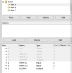
I have designed 3 Symbols for the TL072:
* OpAmp 1 (with Pins In1+, In1- and Out1)
* OpAmp 2 (with Pins In2+, In2- and Out2)
* Power Symbol (with Pins V+ and V-)
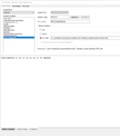
When i try to assign a spice File to the Symbols, i get a pin count error - Of Course: The Spice Model has 5 Inputs for each OpAmp: In+, In-, Out, V+ and V-.
If i add the two power pins to the first two Symbols and make them invisible, the Spice Sim Model can be assigned, but i get a "visibility mismatch error" when saving the library since the visibility for the power pins is different for Symbols 1 and 2 compared to symbol 3.
I also tried to assign the Power Pins to Symbol 0 (like stated in the manual), but that did not solve it, but makes it worse: When i hide a pin, I also hide it in Symbol 3.
So i could just add visible Pins to OpAmp 1 and 2, bit i think that i would get an error, possibly connecting two different nets to the same pin.
I have searched the Internet for the problem and could not find a solution for it. I think I have read all manuals and tutorials from altium, and i have seen every Video about multi parts and spice on YT. I just dont know how i can accomplish to have:
One Component with:
* 3 Symbols (2xOpAmp (without power connectors), 1 Power Con)
* proper footprint
* proper spice models
* without errors.
I know tutorials which teach how to draw a component like the OpAmp - they teach: draw 3 Symbols, like I do.
I also know tutorials which assign spice sims to muilti-part components, but these tutorials are all multiple diodes or resistors without any shared pins. Everybody seems to avoid the problems that i have.
I know that there are other Programs that may be more useful to simulate a circuit, but I would just love to do this right in Altium.
I hope that anybody tried it - and was successful - but even if not - let me know, please!


